
Author: Willem Van Galen

The Include Relationship’s Other Use

Introduction

VanGalen IMG00 JUne18Article [1] outlined the primary use of the include relationship, in which a common set of steps in the specifications of two or more existing use cases are factored out as the specification of a new abstract use case, after which the common steps in the specifications of the existing use cases are replaced with an include relationship to the abstract use case. This article explores the include relationship’s secondary use, where an already existing concrete use case is included in another use case. Throughout, the two patterns are compared and contrasted.

The include mechanism

As per [1], when a concrete base use case includes an abstract use case, it means that at run time the specifications of the two use cases are combined into a single use case specification that governs the behavior of each use case instance in the base use case; the base use case is instantiated, but the included use case is not.

This mechanism follows from the fact that the include relationship is a single relationship between two use case specifications; it does not represent a class of relationships (links) between use case instances, as does an association between two use cases.

The other use

The description under ‘Semantics’ in section 16.3.5 of [2] gave me the impression that the include relationship is solely intended “for reuse of common parts”, that is, for reuse of abstract included use cases (use case fragments, really), as described in  [1]. Since that section doesn’t describe any other use, this impression came easily.

However, an overseas colleague (see Acknowledgement below) pointed out that the section describes this as the ‘primary’ use, so there must also be a ‘secondary’ use, at the very least. As for what that secondary use might be, he pointed to [3] which states that “concrete use cases can […] be included in a base use case.”

That had me puzzled, because didn’t that mean that such an included use case would at the same time have to be concrete (in its own right, capable of being instantiated) and abstract (as an included use case, which doesn’t get instantiated)? Clearly, that is impossible.

(I share this mental block in case others suffer from it as well; the remedy follows.)

Remember the mechanism

The resolution came when I expressed this secondary use in terms of the include mechanism summarized above (substitution in bold):

VanGalen IMG01 JUne18

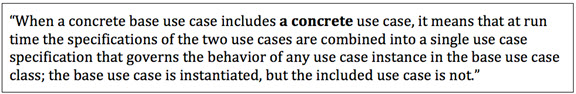
In other words, the fact that during the execution of a base use case neither an abstract included use case nor a concrete included use case gets instantiated, is inherent in the include relationship; it has nothing to do with the included use case being abstract or concrete.

(I feel a lot better now.)

Further considerationsVanGalen IMG02 JUne18

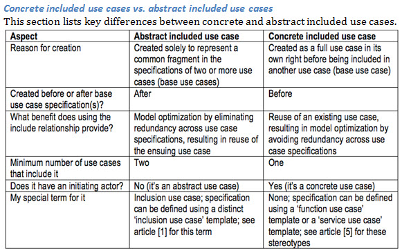
Stay within the system boundary

Article [1] pointed out that include relationships cannot cross system boundaries. Therefore, just like an included abstract use case, an included concrete use case must belong to the system to which the including use case belongs.

This is simply the flip side of the statement in section 16.3.6 of [2], “Two use cases specifying the same [system] cannot be associated since each of them individually describes a complete usage of the [system].”

  • Two use cases of a given system can be connected via an include relationship, but not through an association.
  • Two use cases of different systems can be connected via an association, but not through an include relationship.

In other words, include relationships can only exist within a system boundary and associations can only exist across a system boundary.

Another way to look at this is by realizing that a system encapsulates (does not disclose) its use case specifications. These are for the system’s internal use only, that is, they are used ‘behind’ the system’s public interface. Defining an include relationship across system boundaries would amount to breaking that encapsulation and is therefore inappropriate.

For more on the need to define the system(s) to which use cases apply, see [4]

Include relationship or precondition?

Article [5] distinguishes functional and sequential dependencies between concrete use cases.

  • A functional dependency can be represented by an include relationship between two concrete use cases.
  • A sequential dependency can be represented by one or more postconditions (of the ‘upstream’ concrete use case) and corresponding preconditions (of the ‘downstream’ concrete use case), rather than by an include relationship from the latter to the former.

Concrete use case can be instantiated

A concrete use case that’s also included in a base use case can be instantiated (after all, that’s what defines a concrete use case), but only when it’s initiated by an instance of its initiating actor, outside the context of the base use case in which it is included. At such times, the include relationship between the two is irrelevant.

  • The base use case is functionally dependent on the concrete use case, but the concrete use case is not functionally dependent on the base use case.
  • Hence, any concrete use case instance is governed by the concrete use case’s specification, without any reference to the base use case’s specification.

Which actor and user?

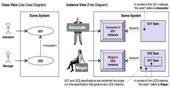
A user (Alex) instantiates a concrete use case (UC1). In the context of the resulting use case instance, any mention of “the actor” in the use case’s specification is a reference to that user (Alex, an Assistant). When another user (Megan) instantiates a second concrete use case (UC2) that includes the first concrete use case (UC1), the specifications of the two use cases combine into a single run time specification for the including concrete use case (UC2). In the context of the resulting use case instance, any mention of “the actor” in the included use case’s specification now is a reference to the other user (Megan, a Manager). See the following diagram.

VanGalen IMG03 JUne18

Writing tip

Because of the above, when writing use case specifications, use “the actor” as the standard way to refer to a use case’s initiating actor (*). In terms of the above example:

  • Don’t write “the Assistant” in the UC1 specification and “the Manager” in the UC2 specification, because that might suggest that a Manager temporarily switches to the role of an Assistant for the duration of the UC1 steps included in UC2, which of course is not so.
  • Which roles a given user can play, that is, to which actors a given user can belong, is solely part of modeling and defining those actors.

(*) Supporting actors are best referred to by name in order to tell them apart from the initiating actor (“the actor”) and from each other (when there are several).

Included use case varieties

Article [1] makes the point that abstract included use cases come in two varieties. These apply to concrete included use cases as well, as follows (see [4] for the stereotypes (*) used below).

  • An included <> use case ends up being a textually included concrete included use case, because it represents a back-and-forth interaction between “the actor” and “the system” during which input data is provided, system data is retrieved, both can be transformed, output data is returned and system data is stored, step by step (i.e., it’s about the steps as well as the ultimate result).
  • An included <> use case ends up being a parameterized concrete included use case, because it accepts one or more input parameters, returns one or more output parameters, and encapsulates (hides) the steps that transform the former into the latter (i.e., it’s about the ultimate result, not about the steps that lead to it).

(*) Even though a <> use case is a concrete use case, I can’t imagine why it would ever be included in another use case.

Other points

Article [1] makes additional points about abstract included use cases that apply equally to concrete included use cases, as follows:

  • Concrete included use cases may be optional. For the reasons outlined in [1].
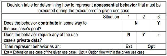
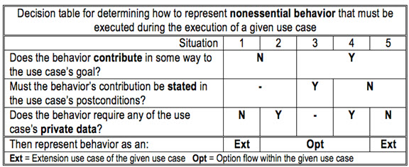
  • Concrete included use cases are not intended for functional decomposition. Including a use case, whether abstract or concrete, amounts to partial functional decomposition of the base use case, but the point is that the included use case wasn’t created for functional decomposition (see table above).

Implementing the include relationship

Article [1] and this article deal with how to understand and use the include relationship as reflected in the UML, where the distinction between classes and instances and the difference between associations, links and relationships are fundamental. Translating the include relationship to constructs in implementation environments depends on the characteristics of those environments and is outside the scope of these articles.

In conclusion

By definition, a concrete use case can be initiated (instantiated) by users (actor instances) outside the system to which it belongs. On the other hand, including a concrete use case represents the direct or indirect inclusion of its specification in the specification of another concrete use case within the system to which they both belong, such that the including concrete use case gets instantiated (as a result of being initiated by a user) but the included concrete use case does not (because it only lends its specification to the including concrete use case).

This pattern can be used, for example, when modeling a component with a number of service use cases, so that a smaller service use case, representing a reusable public service in its own right (e.g., validate credit card), may be included in a larger service use case (e.g., place order).

This article was submitted in the hope that it will contribute to a comprehensive understanding of the include relationship.

Don’t forget to leave your comments below.

Acknowledgement

My thanks to Piermarco Burrafato for bringing this secondary use to my attention.

References
[1] Willem Van Galen, Putting The Inclusion Use Case In Focus, 21 August 2012.

[2] Object Management Group (OMG), OMG Unified Modeling LanguageTM (OMG UML), Superstructure, Version 2.4.1.

[3] Ivar Jacobson, Use Cases: Yesterday, Today, and Tomorrow, 20 November 2003.

[4] Willem Van Galen, The System: Don’t Model A Use Case Without It!, 11 September 2012.

[5] Willem Van Galen, Use Case Preconditions: A Best-Kept Secret?, 15 October 2012.

Excavating The Extension Use Case – Part 3 Nuance

Introduction

Article [1] outlined two considerations for determining whether nonessential use case behavior can be represented as an extension use case, or not. Article [2] introduced a new kind of use case flow for representing nonessential behavior that cannot be represented as an extension use case. In that context, this article adds a further consideration about an aspect not discussed so far. The three considerations are thought to cover most, perhaps even all, possible situations for representing nonessential behavior in a use case model.

Review

The nonessential use case behavior at the heart of this article is behavior that can be executed during a use case’s execution, but that is not essential to reaching the use case’s goal; it can be skipped without affecting the use case’s ability to reach its goal.

Article [1] placed two conditions on representing such behavior as an extension use case of a given use case, which is then called the base use case:

  1. The behavior must in no way contribute to the base use case’s goal.
  2. The behavior must not require access to the base use case’s private data.

Article [2] introduced the option flow concept to represent nonessential behavior that doesn’t meet the above conditions.

These initial aspects are summarized in the following table.

VanGalen March12 img1

Additional nuance

When nonessential behavior in some way contributes to the use case’s goal, the primary reason for representing it as an option flow (*) is to ensure that its result is accounted for in the use case’s postconditions, which would have been impossible had the behavior been represented as an extension use case (see [2] for details).

(*) The secondary reason for representing it as an option flow is when it accesses the use case’s private data, which an extension use case can’t (see [2] for details).

This article adds a nuance to the understanding of nonessential behavior that in some way contributes to a use case’s goal, by recognizing two kinds of such behavior:

  1. The ‘stated contribution’ kind, where the behavior’s contribution is stated as part of the use case’s postconditions, which define how to measure that the use case’s goal has been achieved.
  2. The ‘unstated contribution’ kind, where the behavior’s contribution is not stated as part of the use case’s postconditions, and thus plays no role in measuring whether the use case’s goal has been achieved.

The Coupon option flow in [2] is an example of ‘stated contribution’ behavior, where the use of a valid coupon results in an order discount. 

  • This must be stated in the use case’s postconditions so it can be part of measuring whether the use case’s goal has been achieved.

Examples of ‘unstated contribution’ behavior are the Check Spelling, Change Template and Find Synonym extension use cases mentioned in [3] as extension use cases of the Edit Document base use case.

  • Whether a user of the Edit Document use case corrected the spelling or not, and if she did, whether she used the Check Spelling behavior or spotted and corrected the mistake herself, is unlikely to be stated in the Edit Document use case’s postconditions. The same goes for the other examples.
  • Therefore, and assuming the edited document is considered public data, the Check Spelling, Change Template and Find Synonym behaviors can be represented as extension use cases, because even though they contribute to the Edit Document use case’s goal, their result plays no role in how the achievement of that goal is measured.

The result of combining this consideration with the aspects mentioned earlier is shown in the following table.
VanGalen March12 img2

Note: If you want to avoid the use of an extension use case altogether, you can use an option flow for situations 1 and 5 instead.

Checking against the UML

Even an extension use case that makes an unstated contribution to the base use case’s goal, still upholds the statement in section 16.3.3 of [4] that “the [base] use case is defined independently of the [extension] use case and is meaningful independently of the [extension] use case.” In other words, the base use case in no way depends on the extension use case to reach its goal, according to how the goal’s achievement is defined by the base use case’s postconditions.

In conclusion

How often we may encounter nonessential ‘unstated contribution’ behavior remains to be seen. It might depend on the kind of application being modeled (e.g., the above examples are related to a word processing application). Such behavior may be less prevalent in transaction-oriented applications, such as a webstore application, which is implied in the Coupon option flow in [2].

In any case, it is my hope that this article and the referenced ones will help towards distinguishing essential behavior from nonessential behavior, and representing each in a use case model with clarity, consistency, and conformance to the UML.

Note

The term “base use case” only applies in the context of a use case relationship (e.g., in the context of an extend relationship, it refers to the extended use case). For ease of reference, I have used the term here also to refer to a ‘candidate’ base use case, even when, after further consideration, it doesn’t end up being an extended use case.

References

[1] Willem Van Galen, Excavating the extension use case, 10 July 2012, (Part 1) and 24 July 2012, (Part 2).

[2] Willem Van Galen, Use Case Goals, Scenarios and Flows, 13 November 2012.

[3] Alistair Cockburn, Writing Effective Use Cases, 12th Printing, November 2004.

[4] Object Management Group (OMG), OMG Unified Modeling LanguageTM (OMG UML), Superstructure, Version 2.4.1.

Don’t forget to leave your comments below.

Use Case Goals, Scenarios and Flows

VanGalenNov13 IMG01Introduction

This article is inspired by two more of Alistair Cockburn’s “gold nuggets” found in his book Writing Effective Use Cases [1].  The first nugget is the idea of a goals hierarchy, which represents, among other things, how the goals of a system’s use cases are derived from and trace back to larger goals of the system’s users.  The second nugget is his “striped trousers” explanation of use case scenarios, which are sequences of use case steps that represent different paths through a use case in pursuit of the use case’s goal.  This article also demonstrates a convention for organizing a use case’s steps based on the established approach of writing use case steps nonredundantly by using flows of different kinds.  It even introduces a new kind of flow and advocates its use over that of the extension use case in specific circumstances.

Goal hierarchies

Cockburn provides a mental model of how people and organizations function on the basis of a hierarchy of goals, where each goal, but at its highest-level belongs to one or more higher-level goals and each goal, but at its lowest-level, breaks down into multiple lower-level goals.

  • Moving down the hierarchy answers “How?” to show how a certain goal can be achieved.
  • Moving up the hierarchy answers “Why?” and provides a rationale for why a certain goal exists.

These goals are pursued by different role players (people), organizations (groups of people) and systems (automated resources) inside and outside an organization.

Use case goals

A use case arises when a person (or a system) with an overall goal needs to interact with a supporting system in order to achieve a mini goal as a step towards reaching the overall goal.  The use case represents the supporting system’s ability to deliver the user’s mini goal, and this it the use case’s overall goal.  This can be reflected no more clearly than by naming the use case after that goal.  The use case’s specification details how the use case’s overall goal is broken down into its own mini goals, represented by steps and groups of steps.

Thus, the user’s overall goal, the user’s mini goal/use case’s overall goal, and the use case’s mini goals are seamlessly incorporated into an organization’s goals hierarchy.

The beauty of this perspective is that:

  • System use cases arise from and trace back to the goals of a system’s users, rather than a use case modeler’s imagination.
  • The idea of a goals hierarchy that integrates the goals of groups of people with the goals of people, the goals of people with the goals of supporting systems, and the goals of supporting systems with the goals of their internal steps provides a single paradigm for how an organization functions across all of its levels in both manual and automated ways.

Use case scenarios

A use case scenario is a sequence of steps that represents a single use case execution (a scenario is a possible path through a use case specification).

Cockburn presents a diagram (Figure 2.2 in [1]), whose originality and quirkiness are only exceeded by its effectiveness. He calls it the “striped trousers” view of a use case and its scenarios. In it:

  • The belt represents “the [use case] goal that holds all the scenarios together.”
  • One leg “is for the scenarios that end in success.”
  • The other leg “is for the scenarios that end in failure.”
  • “Each stripe corresponds to a scenario.”
  • “The first stripe on the success leg [is] the main success scenario.”
  • “The leg’s remaining stripes are [all] other scenarios that ultimately end in success – some through alternate success paths and some after recovering from an intermediate failure.”
  • The stripes on the failure leg are scenarios that encounter one or more intermediate failures, possibly recover from some, but always fail eventually.

As Cockburn says, this model “is useful for keeping in mind that every use case has two exits, that the [initiating] actor’s goal binds all the scenarios, and that every scenario is a simple description of the [use case] succeeding or failing.”

This strikes me as one of the greatest contributions to use case modeling.

Use case flows

Cockburn points out, “We won’t actually write every scenario separately from top to bottom.  That is a poor strategy because it is tedious, redundant, and hard to maintain.”

Instead, a use case can be written nonredundantly, starting with an unconditional main flow that is subsequently enhanced with conditional additional flows of different kinds, where a flow is a sequence of steps.  The main flow equates to “the main success scenario” and each additional flow represents a portion of one or more of the remaining scenarios.

The UML doesn’t deal with flows.  Cockburn only refers to “the main success scenario” (main flow) and “extensions” (additional flows).  Refining this view, the following sections present five different kinds of flow by providing a definition, diagram and simplified example for each.  The purpose of the examples is to illustrate a clear, consistent and scalable writing convention for representing a use case’s structure (they’re not meant as full-fledged use case specifications).

The main flow

Definition: An unconditional set of steps that describe how the use case goal can be achieved and all related stakeholder interests can be satisfied.  Each step is essential to achieving the use case goal (no step can be skipped), and each step succeeds.VanGalenNov13 IMG02

Cockburn calls this “the main success scenario,” and others use the terms “the happy path,” “the basic flow” and “the normal course of events.”  My preference is for “the main flow” because it’s short and ties in well with the names of the other kinds of flow.

The next four sections outline what collectively can be called additional flows.

An alternative flow

Definition: A conditional set of steps that are an alternative to one or more steps in another flow (the alternative flow is performed instead of the other step or steps), after which the use case continues to pursue its goal.VanGalenNov13 IMG03

A recovery flow

Definition: A conditional set of steps that are a response to the failure of a step in another flow (the recovery flow is performed after the other step), after which the use case continues to pursue its goal.VanGalenNov13 IMG06

An exception flow

Definition: A conditional set of steps that are a response to the failure of a step in another flow (the exception flow is performed after the other step), after which the use case abandons the pursuit of its goal.VanGalenNov13 IMG07

An option flow

Definition: A conditional set of steps that represent a nonessential option available between two steps in another flow (the option flow is performed between the two steps), after which the use case continues with the second of those steps.VanGalenNov13 IMG08

The option flow’s main purpose is to represent behavior that is nonessential to achieving the use case goal (the behavior can be skipped) but that still contributes to that goal in some way (the behavior only has meaning in the context of that goal).

An “option” is like an optional feature in a new car (e.g., sun roof).  Choosing the option contributes to the goal (order a car), but you can order a car with or without the option (a sun roof is not essential).  Continuing the analogy for another term in this article, a car’s possible engine sizes beyond the standard size are “alternatives” to the standard size (but having an engine of some size is essential).

On point markers

Before taking a closer look at the option flow, here are some comments about branch point markers and rejoin point markers.

Advantages.

  • There is no need to reference actual step numbers (the convention used in [1]); these change when steps are added, deleted or reordered, and if we forget to update their references then the use case becomes corrupted.
  • A flow’s branch points and rejoin points are immediately obvious from the flow’s own description, rather than only from the descriptions of the additional flows that branch off the flow (the convention used in [1]).

Placement of branch point markers. 

  • As the examples show, a branch point marker for an alternative, recovery or exception flow is attached to a main flow step, rather than placed before or after the step; this keeps markers from visually dominating the main flow.
  • This doesn’t apply to the option flow, which by its very nature occurs between two steps.

More on the option flow

What an option flow is not

An option flow is not:

  • Part of the main flow, because an option flow is conditional and nonessential to achieving the use case goal, which is the very opposite of the main flow.
  • An alternative flow, because an option flow isn’t an alternative to a step or steps.
  • A recovery flow, because an option flow is not a response to a failed step.
  • An exception flow, because an option flow is not a response to a failed step and doesn’t mean the use case failed.

Use an extension use case instead?

You may wonder whether nonessential goal-related behavior can be represented as an extension use case instead, given the UML’s extension use case description in [2].  To help answer that, the next table lists key UML statements about the extension use case and their applicability to the option flow.VanGalenNov13 IMG09

At first blush, the above, and in particular its first two statements, suggests it’s reasonable to represent nonessential goal-related behavior as an extension use case.  However, for a conclusive answer, we turn to the extension use case interpretation outlined in [3].

When to use an option flow and when to use an extension use case

Based on [3], the next table repeats when behavior can be modeled as an extension use case and gives answers for the behavior of the earlier Coupon option flow.VanGalenNov13 IMG10

Regarding the False answers for the Coupon option flow behavior:

  1. The third answer is soft: the order could be declared public data, which would change the answer to True.
  2. The first answer is hard: it is and remains a fact that the Coupon option flow behavior contributes to the use case goal, so the answer is always False.

This leads to the following conclusion:

  • Nonessential behavior that in some way contributes to the use case goal must always be modeled as an option flow and never as an extension use case.
  • Nonessential behavior that doesn’t contribute to the use case goal in any way may be modeled as an extension use case (when all three questions are answered with True) or as an option flow (when the third question is answered with False).

Other differences between the option flow and the extension use case

Key to the above conclusion is whether nonessential behavior contributes in some way to a use case’s goal or not.  When it does, using an option flow has undeniable advantages over even thinking about using an extension use case.  These aren’t considered in [3] but do reinforce the above conclusion, which is based on [3], as shown in the following table.VanGalenNov13 IMG11

Thus, the extension use case turns out to be an inappropriate choice for modeling nonessential goal-related behavior; in contrast, the option flow is ideal for this.

Benefits of using the option flow

Ease of producing use case models: 

  • Only need to model one use case for a given goal, not two or more (prevents “use case bloat”).
  • No need to use the special extension use case construct, its involved UML diagramming convention and a custom writing convention; in contrast, writing an option flow and its branch and rejoin points follows the convention used for all additional flows.

Ease of consuming use case models:

  • It’s easier to consume one use case for a given goal than two or more (most consumers will agree with this).
  • A use case’s postconditions and scenarios are all in one place (great for all consumers, but especially for testers).

In conclusion

It is my hope that this article will contribute to crisp, clear and consistent use case models (including diagrams and specifications), and will benefit their producers and consumers, as well as the organizational benefit of their employers.

References

[1] Alistair Cockburn, Writing Effective Use Cases, 12th Printing, November 2004.

[2] Object Management Group (OMG), OMG Unified Modeling LanguageTM (OMG UML), Superstructure, Version 2.4.1, Section 16.3.3, Description.

[3] Willem Van Galen, Excavating the extension use case, 10 July 2012,  (Part 1) and 24 July 2012, (Part 2).

Don’t forget to leave your comments below.

Use Case Preconditions: A Best-Kept Secret?

Introduction

WillOct15th1Alistair Cockburn opened my eyes to the essence, elegance and effectiveness of use case preconditions.  In [1], he discusses preconditions in just a dozen paragraphs, but these contain two statements that revolutionized my understanding of preconditions and their counterpart, postconditions.

This article starts with those statements, illustrates what I believe they imply, outlines key fundamentals, discusses how preconditions and postconditions reflect sequential use case dependencies and promote loose coupling between use cases, and ends with a reflection on enforcing preconditions.

Based on personal experience, as well as a cursory check of the Internet, use case preconditions still seem to be a best-kept secret.  This article is intended to help change that.

Bless you, Alistair

Odd as it seems in retrospect, until I read Alistair Cockburn’s inspiring book [1], use case preconditions were in my blind spot.  That changed with two statements at the start of the book’s chapter 6:

  • “[A use case’s preconditions indicate] what the system will ensure is true before letting the use case start.”*
  • “Generally, a precondition indicates that some other use case has already run to set it up.”

After reading these two statements, the clouds parted, an angelic chorus hummed a mystical chord, and a bright eco-friendly light bulb appeared above my head; I had discovered a nugget in Alistair’s gold mine of a book.

* A use case’s postconditions indicate what will be true after the use case finishes.

A picture tells the story

The next diagram illustrates the use of preconditions, using a simplified example.

WillOct15th2

This diagram reflects the preceding two statements in that:

  • A user can only initiate a use case when the system has concluded that the use case’s preconditions are true.
  • A use case’s preconditions result from executing one or more other use cases.

If we imagine a corresponding user interface, the function button that corresponds to a particular use case is enabled (a user can click on it) when the use case’s preconditions are all true, and disabled (grayed out) when at least one of the preconditions is false.

Another way to view this is as part of a “no false hope” strategy. A user is not given the impression that he can complete a certain function use case he can’t (i.e., if the conditions had been enforced as part of the use case instead of as preconditions, and at least one turned out to be false).

Some fundamentals

This section is based on [1] and on personal experience.

A use case’s preconditions can only exist within the system

Since a use case’s preconditions are enforced by “the system,” they can only exist within that system, which wouldn’t be able to detect them otherwise. A use case precondition cannot refer to a condition in the physical world that isn’t represented within the system.

The reflection at the end of this article shows that when it comes to enforcing preconditions, “the system” in its broadest sense refers to “the systems environment.”

A use case’s preconditions are the same for all its scenarios

Since a use case’s preconditions are true before the use case starts, it follows that they apply to whatever scenario* unfolds during an execution of the use case. This is one reason for not bundling multiple user functions into one use case (e.g., bundling Create, Read, Update and Delete functions into a Maintain use case), for they typically have different preconditions (and postconditions).**

* A scenario is a possible path through a use case.

** Moreover, it’s impossible to show in a use case diagram differences in user authorization; if one role (actor) is authorized to initiate one set of the bundled functions and another role (actor) is authorized to initiate a different set.

A use case doesn’t check its preconditions

Since a use case’s preconditions are “enforced by the system and known to be true” by the time the system allows the use case to start, they are “not checked again during the use case’s execution.”  This is why:

  • Preconditions are also called assumptions (a use case assumes they’re true).
  • There is no need to write use case steps that check preconditions (doing so would miss the point of using preconditions).

Being mindful of these fundamentals yields clear preconditions and use case flows.

Of use case dependencies

Sequential dependencies

A use case precondition reflects a sequential dependency between use cases.

  • Use case B with precondition C can only start after use case A has produced C as a postcondition.
  • Use case B is executed after use case A; their connection is asynchronous.

Functional dependencies

In contrast, an include relationship (and a directed association as well) reflects a functional dependency between use cases.

  • When use case A has an include relationship (or a directed association) to use case B, it means that the functionality of use case B is part of the overall functionality of use case A.
  • Use case B is executed as part of use case A; their connection is synchronous.

Impact on use case models

This difference means it’s incorrect to use a functional relationship to represent a sequential dependency between two use cases—instead, use postconditions and preconditions.  This is summarized in the diagram below for include relationships, using a simplified example.

WillOct15th3

Conditions enable loosely coupled use cases

What is loose coupling again?

Two use cases are loosely coupled when:

  1. The execution of the first enables the execution of the second.
  2. Neither has any knowledge of the other.

Kinds of loose coupling

One kind of loose coupling—between publisher and subscriber use cases connected via event objects and an event manager — is outlined in [2]

A different kind of loose coupling—between upstream and downstream use cases connected via conditions and user actions — is addressed in this section.

Point 1: Function use cases enable function use cases

In the above diagrams, postconditions produced by the execution of one or more upstream use cases enable the execution of one or more downstream use cases.

  • As soon as a downstream use case’s preconditions are all true (i.e., they reflect postconditions produced by the execution of one or more upstream use cases), a user can initiate the downstream use case.

Point 2: Function use cases don’t know each other

In the above diagrams, upstream and downstream use cases don’t know each other.

  • An upstream use case doesn’t know which downstream use cases a user can initiate next.  It doesn’t pass control to any of them.  It only produces certain postconditions.
  • A downstream use case doesn’t know which upstream use cases a user initiated previously.  It doesn’t accept control from any of them.  If initiated by the user, it trusts that its preconditions are true, no matter which use cases produced them.

Actions outside function use cases

As noted earlier, in a use case model the system is understood to take actions outside use cases, for example by ensuring that a use case’s preconditions are true before allowing the use case to start.  Similarly, a user can take actions outside function use cases, for example by selecting an object from a list before initiating another use case.

As setup for an example of the latter, assume that:

  • The personal banking website from the first diagram also has function use cases View Accounts Summary, View Account Transactions, View Account Details and Change Account Details.
  • The postcondition of the customer-centric View Accounts Summary use case is “The user is presented with a summary of the customer’s accounts.”
  • A precondition of the three account-centric use cases is “The account has been identified.”

An implied user action is the selection of an account from the list of accounts presented by the View Accounts Summary use case.  This selection, not the use case, creates the precondition for the three account-centric use cases. 

This user action is implied because it is not part of any of the use cases.

  • Adding it as the final step of the View Accounts Summary use case would make the use case overshoot the user’s goal, which is to view the accounts summary.
  • Adding it as the first step of the account-centric use cases would make using the above precondition impossible and thus undermine the loose coupling between these use cases and the customer-centric one.

The implied system and user actions must be accommodated in the user interface derived from the use case model.

Tip: Don’t state who (an actor) or what (a use case) produced a precondition.

  • Stating an actor introduces irrelevant, distracting and potentially misleading assumptions (what if the use case model is enhanced with a new actor who can also produce the precondition?)
  • Stating a use case violates the principle that loosely coupled use cases don’t know about each other (and what if the use case model is enhanced with a new use case that can also produce the precondition?).

The condition is what matters, not how it came to be.

Benefits

Loose coupling between use cases in general:

  • Inherently leads to use case models that are easy to create, understand and evolve.

Loose coupling between function use cases in particular:

  • Enables analysts to produce use case models without built-in assumptions about the corresponding user interface (e.g., the sequence in which functions get presented).
  • Gives user interface designers the greatest freedom in designing that user interface (e.g., a given function may be launched from multiple screens that each in its own way ensures that the preconditions of the corresponding function use case are met).
  • Allows user interface designers to restructure an existing user interface without the need to change the corresponding use case model (e.g., moving function buttons around but adding no new functions).

Using conditions and user actions to model loosely coupled function use cases results in a highly modularized use case model whose function use cases are:

  • Context-aware (aware of their preconditions, but not of other use cases).
  • Single-purpose (because defining one set of preconditions for multiple purposes usually doesn’t work).
  • Lean (because they are single-purpose and their preconditions are assumed).

When a system is modeled like this, it truly reflects the notion that the use cases represent the system’s operations, as mentioned in [3], because each use case represents a distinct capability the system provides to its users.

Preconditions for other use case types

The preceding deals with function use cases, but preconditions and postconditions can be used for the following use case types as well.

  • Batch process (<>) use case.  As for a function use case, the preconditions reflect the use case’s sequential dependency on one or more other use cases. 
  • Subscriber service (<>) use case.  As outlined in [2], use cases of this type are inherently modeled to be initiated by the event manager, and so they assume the event manager as their context.  This means they have a standard set of preconditions (see [2]).

What enforces use case preconditions?

It’s one thing to state that the system ensures a use case’s preconditions are true before allowing the use case to start, but in a logical use case model it is typically implied that the controller is part of the system.

For a comprehensive understanding of controllers, we have to consider the physical implementation realm as well.  The following table summarizes typical controllers and, relating the physical to the logical, the types of use case they control.

WillOct15th4

This summary shows that the enforcer of a use case’s preconditions isn’t necessarily part of the system to which the use case applies, so in the broadest sense “the system” means the systems environment when it comes to enforcing preconditions.

In conclusion

If you’re new to use case preconditions, I hope this article has whetted your appetite for them.  If you’ve used preconditions before, I trust this article reconfirmed their usefulness and maybe even added a new angle.  Preconditions certainly aren’t the only gold nugget in [1], and perhaps there’ll be opportunity to reflect on others.

Don’t forget to leave your comments below.


 References

[1] Alistair Cockburn, Writing Effective Use Cases, 12th Printing, November 2004.

[2] Willem Van Galen, Modeling Loosely Coupled Use Cases, 30 April 2012, http://www.batimes.com/articles/modeling-loosely-coupled-use-cases.html.

[3] Willem Van Galen, The System: Don’t Model A Use Case Without It!, 11 September 2012, http://www.batimes.com/articles/the-system-dont-model-a-use-case-without-it.html.

The System: Don’t Model a Use Case Without It!

FEATURESept11thIntroduction

After getting involved in use case modeling many years ago, I was surprised to learn that some people had no qualms about modeling a use case without defining the “system” whose behavior the use case represented, even though there is a UML notation for it.  Today, the Internet contains many use case diagrams that lack any sense of “the system” (thankfully, it also contains many that do depict and name it). 

This article presents four questions that point to key reasons for defining a use case’s system, and three subtle aspects of representing systems in use case models.

Note: Section 16.1 of [1] uses “subject” to refer to “the system under consideration to which the use cases apply.”  This article uses “system” instead.  See also (*) of the second question below.

1.  Without a system, …

… what are actors interacting with?

According to section 16.3.1 of [1], a use case’s actor (class) represents an entity (instance) that “interacts with the [system]” and that is “external to the [system]”.  The use case, which is internal to the system, specifies how the interaction can take place and what its results can be, but is not something actor instances interact with.

It’s impossible to define a proper use case model if we don’t honor this fundamental notion from the start by defining “the system under consideration to which the use cases apply” (section 16.1 of [1]) in use case diagrams and use case specifications.


Tip: When you draw a use case diagram, always start by drawing and naming the system whose behavior is represented by the use cases to be added to that diagram.

… what is the boundary of a use case model?

In a way, the term “use case modeling” is unfortunate, because in the end it is not about modeling individual use cases but about modeling a particular system, such that each system has its own use case model.

Obviously, we can’t define a system’s use case model if we don’t have a clear sense of what that system is to begin with.

Tip: Just like in class modeling it’s impossible to define an operation without first defining the class that owns the operation, in use case modeling (or “system modeling”) we ought to consider it impossible to define a use case without first defining the system to which the use case applies (*), because, essentially, a use case represents an “operation” of a system (**).

(*)  It would go too far right now to explore the UML’s distinction between a use case’s “subject” (to which the use case applies) and a use case’s “owner” (that owns the use case).  For the purpose of this article, the “subject” and the “owner” are one and the same and represented as the “system”.

(**)  According to section 16.3.6 in [1], a use case “need not be attached to any specific subject [(system)].”  That strikes me as peculiar, because in explaining the use case concept, the description in the same section refers to a use case’s subject (system) no less than twelve times!  The gist of this article is that, for all practical intents and purposes, each use case ought to apply to a certain system.

… what constrains the use of include relationships?

As demonstrated in [2], an include relationship can only be used within a system.

Therefore, we can’t be sure we’re using include relationships properly if we have no clear idea of a system’s boundary.  See [2] for an additional constraint.

… how can we define a logical application systems architecture?

Influenced most recently by service-orientation, an organization’s application systems domain can be divided into architectural layers.  The top layer supports business processes and is itself supported by several underlying component layers.

A fundamental rule is “call down only”, so that a system in a higher layer can initiate an interaction with a system in any lower layer, but not the other way around.

Use case models can represent the logical (technology-neutral) view of this domain.

The following table summarizes 4 of the 5 layers from [3], in order to show how each “system” in these layers can be represented by its own use case model.

WillemTab1

Without defining a use case’s system, we have no clear idea about the use case’s place in the systems architecture and we’d be modeling the use case in a vacuum.In this article, it’s not about the precise layers (different organizations favor different layers) but about having a layered systems architecture to begin with.

However, a use case’s system doesn’t magically appear when we start use case modeling during a project.  As this section aims to illustrate, that system must be defined and justified in an organization’s systems architecture before we know we need a use case model for it at all, let alone what its use cases ought to be.

2.  Representing systems in use case models

The previous section moved from the need to identify the system for a single use case to the need to identify such systems for an entire organization.  This section deals with some of the subtler aspects of representing (the connection between) systems in use case models.

Connections between systems: a notational wrinkle

Point 3 of [2] hints at a wrinkle in the UML representation of the connection between two systems.  This wrinkle can be summarized visually as follows (*).

WillemSept10th1

The bottom view is perfectly in tune with the specification of Some Application Function Use Case, which at some point contains the step, “Initiate Some Service Use Case of Some Component.” (**)  Without that step, there would be no justification of why Some Component is a supporting actor of Some Application Function Use Case, and no clarification of where and how Some Component supports that use case.

(*)  The <> stereotype (short for “application function”) is for interactive use cases with a human initiating actor, while the <> stereotype is for use cases with an electronic initiating actor.  See also the first reply attached to [2].

(**)  The step is not written as, “Include …”, because the two use cases are connected via an association, not an include relationship (see [2] for details).

The next aspect is about getting one step closer to representing that a connection between two systems is in the end a connection between two of their use cases.

Generic initiating actor for service use cases

In the Some Component’s use case diagram above, the service use case’s initiating actor is shown specifically as Some Application, but this is only done to make the point represented by the bottom picture.  Like object operations, service use cases don’t assume context, because they are reusable by current and future consumers, in unpredictable contexts.  As a service use case sees it, its initiating actor is generic.

To reflect this in a use case model, I use “Electronic Function” as the initiating actor of every service use case.  This actor represents any set of electronic instructions, such as interactive application functions, batch applications, and services.  These are typical service consumers.  This evolves the use case diagram to the following.

WillemSept10th2

An alternative is to name the generic actor after the role these electronic functions play vis-à-vis a service use case, like “Service Consumer”.  Still, I prefer “Electronic Function”, because it’s a more direct and obvious representation than “Service Consumer” (the former reflects the actor’s nature, whereas the latter doesn’t), and “Service Consumer” is redundant and therefore doesn’t add anything (the fact that it’s the initiating actor of a service use case already shows it’s a service consumer).

In use case models, a specific Electronic Function is represented as a use case.

Systems can be arranged into hierarchies

One best kept use case modeling secret (*) seems to be that systems can be arranged into hierarchies, where:

  • A lower-level system inherits use cases from its higher-level system(s).
  • A use case of a lower-level system can redefine (augment, constrain, or override) a use case inherited from a higher-level system.
  • Higher-level systems can be abstract, while lowest-level systems are concrete.

This is because in [1], a use case’s system is a Classifier, Classifiers can be arranged into hierarchies of generalized and specialized Classifiers, a specialized Classifier inherits Named Elements from its generalized Classifier(s), and a Use Case is a specialized Named Element.  (Since actors and use cases are also Classifiers, they can each be arranged in hierarchies as well, but this is outside the article’s scope.)

There may not be many opportunities to use this approach (I used it once so far), but it’s good to have this option in our use case modeling toolbox.

(*)  Another one may be revealed in a future article.

In conclusion

It is my hope that this article contributes to understanding the crucial role of systems in use case models (and the crucial role of use case models in the logical representation of systems) and to producing clear and intuitive use case models.

Don’t forget to leave your comments below.


References

[1] Object Management Group (OMG), OMG Unified Modeling LanguageTM (OMG UML), Superstructure, Version 2.4.1, http://www.omg.org/spec/UML/2.4.1/.

[2] Willem Van Galen, Putting the inclusion use case in focus, 21 August 2012, http://www.batimes.com/articles/putting-the-inclusion-use-case-in-focus.html.

[3] Everware-CBDI, Service Architecture Layers, slide 9 of this presentation: http://www.codegeneration.net/cg2007/sessions/slides/EverwareCBDIMetaModelPresentation.ppt.

This article ignores the fifth layer, since it’s not needed to make the related point.

Essentially, there are two conventions for using the term “service”.

  1. 1.A “service” refers to a container and its operations are its “capabilities”.
  2. 2.The container is called a “component” and its operations are its “services”.

The above presentation uses the first.  In contrast, I use the second, as it strikes me as more intuitive (“service” refers to the service provided, not the service provider).