
Author: Willem Van Galen

Putting The Inclusion Use Case In Focus

FEATUREAug21stIntroduction

The circumstances that made me analyze the extension use case from the ground up (see [1]) also led me to examine the inclusion use case.  Like the extension use case, the inclusion use case is at times misinterpreted and misapplied.  Like the extension use case, once it’s understood from first principles, the inclusion use case has a more specialized purpose than is sometimes thought.  This article mentions six fundamental points that contribute to creating quality use case models, with or without inclusion use cases.

Note: Section 16.1 of [2] uses “subject” to refer to “the system under consideration to which the use cases apply.”  This article uses “system” instead.

Point 1: Include relationships cannot cross system boundaries

An include relationship — between a base use case and an inclusion use case — can only be defined between use cases of the same system.

This assertion is based on the following rationale.


Only associations can cross system boundaries

The association is a core element of a system’s use case diagram.

  • An actor is always external to the system and a use case is always internal to the system.
  • An actor and a use case can only be connected through an association, which therefore crosses the system boundary.

This is illustrated in the following diagram, which contains a “directed” association to show the flow of control (the actor initiates the interaction with the system).

WillemAug212

Include relationships are not associations

When use case A of one system can initiate use case B of a second system, then:

  • In the use case diagram of the first system, the second system is shown as a supporting actor of use case A.
  • In the use case diagram of the second system, the first system can be shown as the initiating actor of use case B.

Thus, a relationship between two use cases that crosses system boundaries can only be an association.  Since an include relationship is not an association, it cannot cross system boundaries, and can therefore only be used within a system boundary.

Supportive UML superstructure excerpts

Crucial excerpts from [2] that support the above are:

  • “An Actor models […] an entity that interacts with the [system], but which is external to the [system].”  Section 16.3.1, Description.
  • “An actor can only have associations to use cases […].  Furthermore these associations must be binary.”  Section 16.3.1, Constraints.

Point 2: Actors, associations and use cases are classes

This point connects points 1 and 3.

Classes

An association connects two classes (*).

  • At its simplest, a class is a set of entities (objects, instances) of a certain type.
  • An association represents that an instance in the one class can be connected to an instance in the other class through a link.
  • A link is an instance of an association.

(*)  In the UML an association is between “classifiers”, which is a broad category that includes the narrower (and somewhat informal) “classes” category used here.

Thus, a use case diagram represents a class view, where:

  • An actor is a class of possible actor instances.
  • A use case is a class of possible use case instances.
  • The association between the actor and the use case is a class of links between actor instances and use case instances.

A class view is a model-time view and an instance view is a run-time view.

Throughout this article, “use case” and “use case class” are used interchangeably.

Supportive UML superstructure excerpt

A key excerpt from [2] that supports the above is:

  • “An association describes a set of tuples whose values refer to typed instances.  An instance of an association is called a link.  A link is a tuple with one value for each end of the association, where each value is an instance of the type of the end.”  Section 7.3.3.

Point 3: Inclusion use cases are not real use cases

Key UML superstructure excerpt

Section 16.3.5 of [2] states:

  • “The include relationship is intended to be used when there are common parts of the behavior of two or more use cases [(*)].  This common part is then extracted to a separate use case, to be included by all the base use cases having this part in common.” 

(*)  Based on the preceding, this can be enhanced to “… two or more use cases of a single system.”     

Thus, an inclusion use case is simply a common fragment lifted from two or more use case specifications and defined as the specification of a single inclusion use case.  The inclusion use case is then referenced from the base use case specifications by an include statement in place of the original fragment.

WillemAug213 

Inclusion use cases (and extension use cases) are fragments

Section 16.3.6 of [2] states that a use case “describes a complete usage of the [system]” by an initiating actor.  Since, as shown above, inclusion use cases only represent portions of base use cases, an inclusion use case never “describes a complete usage of the [system]” and is therefore not a real use case.  In [3] Jacobson proposes to call them “fragments” rather than use cases and even suggests a separate notation.  Within the current UML notation, I use the custom-defined <> stereotype for inclusion use cases (and extension use cases as well), as illustrated in the following diagram.   

Inclusion use cases (and extension use cases) are abstract use cases

The UML refers to real and not real use cases as concrete and abstract use cases. 

  • A concrete use case is a use case that can be instantiated.
  • An abstract use case is a use case that cannot be instantiated.

Concrete and abstract use cases in use case diagrams

  1. Any use case that has an association with an initiating actor is a concrete use case (*).
  • At execution time, the initiation of the use case by an actor instance (within the actor class) creates a use case instance (within the use case class) (**). 
  • The use case instance behaves according to the use case specification, which is attached to the use case class and applies to all its instances.
  1. Any use case that does not have an association with an initiating actor is an abstract use case (*).
  • At execution time, the specification of the abstract use case is combined with the specification of a related concrete use case, and the instance of the concrete use case behaves according to the combined specification. 
  • An abstract use case cannot be instantiated, so there will never be a use case instance that is solely based on an abstract use case.

(*)  The exception is a generalized use case, which is outside the scope of this article.

(**)  This applies if the actor is a person.  When the actor is a system, the use case is initiated by an instance of a particular use case of that system, not by an instance of the system itself.

Regarding notation:

  • A concrete use case’s name appears in straight font, an abstract use case’s name in italic font.
  • An include relationship (and an extend relationship as well) appears as a dashed arrow (as opposed to a solid arrow used for a directed association) to convey that the relationship is between the specifications of the related use cases, not between instances of those use cases.

See the above diagram.  

Public and private use cases

Because actors can only initiate a system’s concrete use cases, these are the only use cases that are visible outside the system, while the system’s abstract use cases are invisible outside the system.  Thus, a system’s concrete use cases are its public use cases and the system’s abstract <> use cases are its private use cases. 

A key consequence of this is that if abstract use cases are to be introduced at all, they ought to be introduced after concrete use cases have been defined first.    

Point 4: Inclusion use cases come in two varieties

One variety is the “textually included” inclusion use case.  The inclusion use case’s specification text seamlessly connects with the specification texts of the base use cases, by referring directly to elements within those specification texts by name.  Textually included inclusion use cases are context-aware. 

  • According to section 16.3.5 of [2], “the behavior of the [inclusion] use case is inserted into the behavior of the [base] use case.”
  • For those of us who are old enough to remember, these are like copybooks in a COBOL program’s PROCEDURE DIVISION.

The other variety is the “parameterized” inclusion use case.  The inclusion use case’s context is represented by input parameters, whose values are set by a base use case and used by the inclusion use case.  The inclusion use case’s outcome is represented by output parameters, whose values are set by the inclusion use case and used by a base use case.  Parameterized inclusion use cases are context-agnostic. 

  • Section 16.3.5 of [2] adds, “The [base] use case may only depend on the result (value) of the [inclusion] use case.”
  • Continuing the COBOL analogy, these are like statically called subprograms.

Point 5: Inclusion use cases may be optional

A UML superstructure statement

Section 16.3.5 of [2] states:

  • “Note that the [inclusion] use case is not optional, and is always required for the [base] use case to execute correctly.” 

Cause for confusion

Some seem to interpret this to mean that an inclusion use case must be performed during each and every execution of a base use case. 

Nothing is further from the truth and the truth is simple.

The simple truth

Whether an inclusion use case is mandatory or optional to a base use case depends on where in the base use case the fragment was defined that is now replaced with an include statement for the inclusion use case.

  • If that fragment was part of the base use case’s unconditional flow (steps that always get executed), the inclusion use case is mandatory. 
  • If that fragment was part of a conditional flow (steps that get executed optionally), the inclusion use case is optional.  

So what does the UML statement mean?

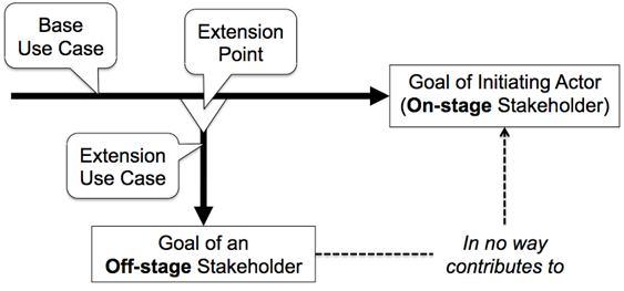
The purpose of the UML statement seems to be to contrast the include relationship with the extend relationship, as follows.

At an extension point (not for the entire base use case), the extension use case’s execution is optional. 

  • When the execution of a base use case reaches an extension point, an extension use case may or may not be inserted, because there may be a condition attached to the extend relationship.

However, at an “inclusion point” (not for the entire base use case), the inclusion use case’s execution is mandatory.

  • When the execution of a base use case reaches an inclusion point (i.e., an include statement in the base use case), the inclusion use case will always be performed, because there is no provision for attaching a condition to the include relationship. 

Point 6: Inclusion use cases are not intended for functional decomposition

The principle of creating an inclusion use case to represent “common parts of the behavior of two or more use cases [of a single system]” is at the same time a key argument against using inclusion use cases for functional decomposition, where a base use case would be decomposed into several inclusion use cases that would be included only in that base use case.  Since such inclusion use cases would not be shared by “two or more use cases”, functional decomposition goes against the above principle. 

This underlines that the key reason for introducing inclusion use cases is to optimize a system’s use case model through re-use of inclusion use cases. 

  • However, care must be taken not to take this to the extreme. 
  • Sometimes it’s “better” to introduce an inclusion use case and sometimes it’s “better” to describe a common fragment in multiple use case specifications.  

In conclusion

These points may seem trivial to some, but being mindful of them inevitably results in better use case models.  In fact, ignoring the first three may cause a larger omission.  Due to space limitations, that must wait until later.

This article is about including an abstract use case, but that’s not the only use of the include relationship.  Article [4] deals with including a concrete use case.

Don’t forget to leave your comments below.


References

[1] Willem Van Galen, Excavating the extension use case, 10 July 2012, (Part 1) and 24 July 2012, (Part 2).

[2] Object Management Group (OMG), OMG Unified Modeling LanguageTM (OMG UML), Superstructure, Version 2.4.1.

[3] Ivar Jacobson, Use Cases: Yesterday, Today, and Tomorrow, 20 November 2003.

[4] Willem Van Galen, The Include Relationship’s Other Use, 19 June 2013.

Excavating The Extension Use Case – Part 2

Introduction

Part 1 of this article revealed the extension use case as a much more specialized construct than commonly suggested. Part 2 increases that notion and deals with some of the consequences of this narrower view of extension use cases.

1Further observations

If the principle of encapsulation is to be upheld, as Rumbaugh suggested in [1], it cannot apply solely to the base use case’s steps but must apply equally to the data manipulated by those steps. The UML provides a convention for declaring an extension point for a base use case in terms of its steps, but I know of no UML convention for declaring which data a base use case makes available at an extension point. Consequently, I must conclude that a base use case’s data is unknown to, and therefore inaccessible by, an extension use case. However, apart from a use case’s private (local) data, there may be public (global) data, which is accessible by all use cases, including extension use cases (e.g., User Id).

Additionally, it seems to me that a condition associated with an extension point must also “belong to” the base use case and not to the extend relationship between the extension use case and the base use case as in the example shown in Figure 16.3 of [2]. In terms of this example, how can the “customer selected HELP” condition arise unless the base use case accommodates it to arise? After all, the base use case describes how, in pursuit of a certain goal, the initiating actor can interact with the system to which the base use case belongs. Actually, I see no need for an “extension condition” when you name an extension point after the condition that has arisen in the base use case at the extension point.


Actually, an extension point should never be named after an action that is assumed to be performed at the extension point (i.e., by an extension use case), because as part 1 of this article explained, the base use case doesn’t know whether it’s being extended at a given extension point, let alone by which extension use case!

Extension use cases without and with actor involvement

In Jacobson’s example cited in part 1 of this article, the base use case’s initiating actor is unaware of the extension use case, because the extension use case doesn’t require the actor’s involvement. However, there are also extension use cases that do involve the actor. This is fine, as long as the goal of the extension use case is perpendicular to that of the base use case, and the extension use case doesn’t require any of the base use case’s private data. This is illustrated in the following diagram.

2

After the “Log In” base use case reaches the “User has been authenticated” extension point, the “Advertise Product” extension use case is given control. The extension use case determines whether, during one of its previous executions, the user chose or declined to be informed about the product. If not, the user chooses one of the following options, which causes the extension use case to take the corresponding action.

2.5

The extension use case then ends and control returns to the base use case.

This behavior can be modeled as an extension use case because its goal in no way contributes to the base use case’s goal, it requires none of the base use case’s private (local) data (e.g., User Password, Security Questions and Answers) and the data it does require has been defined as public (global) data (i.e., User Id).

This extension use case controls an interaction between the system and the base use case’s initiating actor in pursuit of the “Advertise Product” goal of the off-stage stakeholder that is perpendicular to the “Log In” goal of the on-stage stakeholder.

Extension use cases vis-à-vis event-driven architecture (EDA)

Part 1 of this article noted that an extension use case intersects with a base use case at a single condition or event in the base use case. While this is an event-based relationship, an extend relationship is not suited to represent an event-driven relationship as understood in event-driven architecture because it fails to meet at least the following EDA principles described in [3].

Reports current events: A publisher use case is modeled to produce an event object that represents an event as it happens or a condition as it is detected. Mediated by an event manager, the event object triggers one or more subscriber use cases that are modeled to consume the event object.

  • A base use case doesn’t produce an event object, so it’s not a publisher.

  • An extension use case is neither triggered by nor consumes an event object, so it’s not a subscriber.

Late or no binding: An event publisher and event subscriber are not aware of each other’s identities when they are developed or deployed.

  • While a base use case is unaware of an extension use case, an extension use case is aware of the base use case and its extension point from the moment the extension use case is modeled because it owns the relationship with the base use case.

Moreover, the relationship between a publisher and a subscriber use case is asynchronous (the latter doesn’t execute as part of the former), whereas the relationship between an extension use case and a base use case is synchronous (the former executes as part of the latter).

My first article [4] outlines an approach for modeling publisher and subscriber use cases that requires neither extension use cases nor inclusion use cases.

Summary of this article’s considerations

The table below summarizes the considerations identified thus far.  The concluding article [6] adds one more consideration, based on the article [5] that precedes it.

3

(*) If/when there is a convention for declaring certain of a base use case’s private data as publicly accessible at an extension point, model the behavior as an extension use case.

(**) This implies that the behavior’s goal contributes in some way to the base use case’s goal in the eyes of the use case’s initiating actor.

Note

The term “base use case” only applies in the context of a use case relationship (e.g., in the context of an extend relationship, it refers to the extended use case). For ease of reference, I have used the term here also to refer to a ‘candidate’ base use case, even when, after further consideration, it doesn’t end up being an extended use case.

Don’t forget to leave your comments below.


References

[1] Ivar Jacobson, Use Cases: Yesterday, Today, and Tomorrow, 20 November 2003, found at http://www.ibm.com/developerworks/rational/library/775.html (page no longer exists; see: http://www.spinsp.org.br/grupo/Future_%20of_Cases.pdf).

[2] Object Management Group (OMG), OMG Unified Modeling LanguageTM (OMG UML), Superstructure, Version 2.4.1, Section 16.3.3, Description.

[3] W. Roy Schulte et al., Smart Devices and Sense-and-Respond Systems Are Event-Driven, 12 October 2009, Gartner, Inc.

[4] Willem Van Galen, Modeling Loosely Coupled Use Cases, 30 April 2012, http://www.batimes.com/articles/modeling-loosely-coupled-use-cases.html.

[5] Willem Van Galen, Use Case Goals, Scenarios and Flows, 13 November 2012, http://www.batimes.com/articles/use-case-goals-scenarios-and-flows.html.

[6] Willem Van Galen, Excavating the extension use case, Part 3, 12 March 2013, http://www.batimes.com/articles/excavating-the-extension-use-case-part-3-nuance.html

Excavating The Extension Use Case

Introduction

Several years ago, I was asked to create a use case modeling course. This set me off on “an archeological dig” of the use case domain, scraping away layers of vague, confusing and sometimes WVGJuly10th1contradictory information until I hit bedrock. The construct for which I felt the greatest need to do this is the extension use case (a close second was the inclusion use case, but that’s perhaps for another time).  In this two-part article, I summarize my exploration and share my interpretation of what I found. 

My impression is that the extension use case is often misunderstood and misapplied, which may lead to confusing inconsistencies and counterproductive debates. However, understood from the ground up, the subjectivity that drives its traditional use gives way to an objectivity that guides its further application.

Scraping the surface: the typical explanation

An extension use case is often explained as representing behavior that is “optional” to a base use case, where some executions of the base use case will trigger the extension use case and others will not. This explanation didn’t sit well with me, because why couldn’t such optional behavior be represented as an alternative flow in the base use case? An alternative flow and an extension use case are both responses to a condition or event that occurs at a certain point in the base use case, so when do you use the one and when the other?

Digging sideways and down: Alistair Cockburn

Cockburn [2] advocates the use of extension use cases when “there are many […] interrupting services the user might use” (e.g., “Check spelling,” ”Change template” and “Find synonym” are extension use cases of the “Edit document” base use case) and “when you are writing additions to a locked requirements document.” 

  • The first reason refers to behaviors that are “optional” to the base use case, but Cockburn’s example implies that “optional” means non-essential to reaching the base use case’s goal, because you can complete the “Edit document” use case countless times without ever triggering any of the extension use cases.
  • The second reason strikes me as arbitrary because here the use of extension use cases is driven by project circumstances rather than by the nature of the system being modeled.

Cockburn also provides some valuable concepts. The following are relevant to this article.

  1. Goal orientation. Each actor-initiated use case represents, and is named after, a single goal of the initiating actor. In order to reach the goal, the actor needs the assistance of the system to which the use case belongs. Each step of the use case’s main flow and alternative flows is a mini goal toward reaching the initiating actor’s goal (this does not apply to exception flows, which represent failures to reach the goal).
  2. Off-stage stakeholder. “A use case captures a contract between the stakeholders of a system about its behavior.” A use case’s initiating actor can be called an on-stage stakeholder because the actor is directly involved in the use case’s execution. An off-stage stakeholder is not directly involved in the execution of a use case, but does have interests the use case needs to address.

We’ll return to these concepts momentarily.

Digging deeper: the UML

The UML superstructure [1] refers to an extension use case as behavior that is “usually supplementary” to a base use case. That’s different from “optional,” when “supplementary” is understood to mean “additional,” as will become clear. The description is worth quoting in its entirety.

“This relationship specifies that the behavior of a use case may be extended by the behavior of another (usually supplementary) use case. The extension takes place at one or more specific extension points defined in the extended use case. Note, however, that the extended use case is defined independently of the extending use case and is meaningful independently of the extending use case. On the other hand, the extending use case typically defines behavior that may not necessarily be meaningful by itself. Instead, the extending use case defines a set of modular behavior increments that augment an execution of the extended use case under specific conditions.”

This description also conveys the key notions that a base use case “is defined independently” of an extension use case and “is meaningful independently” of an extension use case. Different people interpret these statements differently; my interpretation follows shortly.  

While this description hints at the extension mechanism, it doesn’t strike me as a clear indication of when to use it.

Hitting bedrock: Ivar Jacobson

Jacobson wrote two articles [3] that for me brought home the extension use case concept. In [3] he provides the original example he used to explain the extension use case idea. Set in a telecommunications context, it includes a base use case, Call Handling, that represents a Subscriber making a phone call, and an extension use case, Traffic Recording, “the goal of which is to measure the average traffic from subscribers during, say, a 15-minute period.” The caption of Figure 2 in [3] is, “With a simple technique—separation of concerns with extensions and extension points—the Call Handling [base] use case could become oblivious of the Traffic Recording [extension] use case.”  

The concerns being separated are making a phone call and gathering phone call traffic data. What I find crucial here is that in Cockburn’s terms:

  1. These are concerns, or goals, of different stakeholders. Of the Subscriber as the on-stage stakeholder on the one hand and of a department in the Organization as an off-stage stakeholder on the other.
  2. The goal of the extension use case in no way contributes to the goal of the base use case. The extension use case is not a mini goal, whether mandatory or optional, toward reaching the base use case’s goal as the Subscriber sees

As far as the Subscriber is concerned, the extension use case doesn’t even exist! 

So the need for an extension use case is driven by separate concerns or goals, of different stakeholders, that are perpendicular to each other and intersect only at a single condition or event in a base use case, that is of interest to both. The goal of an extension use case cuts across (is perpendicular to) the goal of any use case it extends. This is represented visually in the diagram below.

WVGJuly10th2

I believe that’s why Jacobson states that the base use case has “become oblivious” of the extension use case (the extension use case in no way contributes to the goal of the base use case), and why the UML description states that “the [base] use case is defined independently of the [extension] use case and is meaningful independently of the [extension] use case” (in the eyes of the base use case’s initiating actor, who doesn’t necessarily know the extension use case exists). 

In fact, a base use case doesn’t even know whether it’s being extended at a given extension point, let alone by which extension use case!

In [4] Jacobson relates an interesting exchange he and James Rumbaugh had when they were working on UML 1.1. In Jacobson’s example mentioned above, the base use case is an open book and the extension use case defines the extension point by referring to a specific step in the base use case. Rumbaugh saw this as “breaking encapsulation” of the base use case (referring to its inner details from the outside). 

To avoid this he suggested that an extension point “belongs to” the base use case, not to the extension use case. Thus the extension use case would only see the base use case’s public extension point and be “oblivious” of the base use case’s private details. “If you changed the [base] use case, [Rumbaugh] said, only that use case would know the [extension point’s] new location.” Jacobson concludes, “I agreed with him.”

So not only is a base use case “oblivious” of the existence of an extension use case, an extension use case is also “oblivious” of the internals of a base use case it extends.

Part 2 of this article elaborates on this. 

In conclusion

This “archeological dig” revealed to me that the extension use case is a more specialized construct than commonly suggested. Part 2 of this article increases that notion and deals with some of the consequences of this narrower view of extension use cases.

Note

The term “base use case” only applies in the context of a use case relationship (e.g., in the context of an extend relationship, it refers to the extended use case). For ease of reference, I have used the term here also to refer to a ‘candidate’ base use case, even when, after further consideration, it doesn’t end up being an extended use case.

References

[1] Object Management Group (OMG), OMG Unified Modeling LanguageTM (OMG UML), Superstructure, Version 2.4.1, Section 16.3.3, Description.

[2] Alistair Cockburn, Writing Effective Use Cases, 12th Printing, November 2004.

[3] Ivar Jacobson, Use Cases and Aspects – Working Seamlessly Together, Journal Of Object Technology, Vol. 2, No. 4, July-August 2003.

[4] Ivar Jacobson, Use Cases: Yesterday, Today, and Tomorrow, 20 November 2003, found at http://www.ibm.com/developerworks/rational/library/775.html (page no longer exists; see: http://www.spinsp.org.br/grupo/Future_%20of_Cases.pdf).

Modeling Loosely Coupled Use Cases

Introduction

Last year, I got my first exposure to event-driven architecture (EDA), courtesy of several systems architects in our organization. Our systems architects operate in the “physical” (technology-specific) realm, whereas our systems analysts are active in the “logical” (technology-neutral) world. As a systems analyst, I became interested in how we could take advantage of EDA in our logical deliverables (why should architects have all the fun?). This article outlines a standard approach for representing basic EDA aspects in system use case models. A major inspiration for this approach is the wonderful article “How EDA extends SOA and why it is important” by Jack van Hoof. If you’re unfamiliar with this article, I encourage you to read it.

Use Case Coupling Patterns

As it turns out, there are two fundamental ways in which use cases can be coupled: command-and-control and publish-and-subscribe.

The command-and-control pattern covers scenarios where one use case initiates (not includes; see Postscript below) another use case (and that use case may initiate another use case, and so on). Any initiated use case gets executed as part of the initiating use case. They execute synchronously. An initiating use case knows an initiated use case by name (the reverse is not true). They are tightly coupled. They form a hierarchy of “superior” and “subordinate” use cases. An initiating use case controls the activation of initiated use cases (an initiating use case “is the boss of” its initiated use cases). This pattern is about functional request-and-reply processes.

The publish-and-subscribe pattern covers scenarios where (i) a “publisher” use case publishes, as an event object, an event of a certain type that took place during the use case’s execution, and (ii) one or more “subscriber” use cases that subscribe to events of that type get initiated and passed the event object.  Any subscriber use case gets initiated and executed separately from the publisher use case. They execute asynchronously. No publisher use case knows any subscribing use case by name (the reverse is true as well). They are loosely coupled. They form a network of “upstream” and “downstream” use cases. No publisher use case controls the activation of subscriber use cases (no publisher use case “is the boss of” any subscriber use case). This pattern is about workflow processes.  

Key questions are, of course:

  • What facility accepts the event object from a publisher use case and passes it to the subscriber use case(s)?
  • How does this facility know to which subscriber use case(s) it must pass a given event object and when?

Event Manager

To address these questions, we introduced the Event Manager as a logical system (i.e., represented by its own use case model). The Event Manager is separate from all other logically represented systems (i.e., that all have their own use case models) but is instrumental in connecting (use cases of) these systems into a network. (I use the generic term “system” to denote either a traditional system or, in a service-oriented context, a component; either classification works for the Event Manager.) This is summarized visually in Figure 1.

May1 vangalen graph1

Figure 1: Consolidated use case diagram with Event Manager

Event Type Registry

The Event Manager is the keeper of the Event Type Registry. This registry contains:

  1. The modeled event types. These are the event types the Event Manager recognizes.
  2. Attributes for all event types. These are the common attributes that apply to all event types, such as event type, date/time published, publisher use case identifier (see also point 4 below). At minimum, each event object provides attribute values for those attributes.    
  3. Attributes by event type. Each modeled event type may have its own mandatory and/or optional attributes that represent the data to be published about an individual event of that type. Each event object of that type provides attribute values for those attributes.
  4. Publishers by event type. For each modeled event type, one or more use cases that are modeled to publish events of that type. Each publisher use case is identified by the name of the system to which it applies (its “subject” in UML terms) plus its use case name.  
  5. Subscribers by event type. For each modeled event type, one or more use cases that are modeled to subscribe to events of that type. Subscriber use cases are identified in the same way as publisher use cases.
  6. Subscriber notification requirements by event type. For each event type/subscriber combination, an indication of when the subscriber use case must be notified following the publication of an event of that type (e.g., immediately, overnight). These are part of the subscriber use case’s service-level requirements.

This registry is the central location where systems analysts record the modeling decisions they make when they apply the publish-and-subscribe pattern to model loosely coupled use cases to represent asynchronous system processes.

Event Manager Use Cases

Since the Event Manager is a logical system, it’s instructive to represent it through its own use case model. Figure 2 shows the model’s use case diagram.

May1 vangalen graph2

Figure 2: Event Manager’s use case diagram

The Event Manager’s two use cases can be summarized as follows.

  1. Publish an Event. This is a “service” use case (i.e., initiated by [a use case of] another system). The use case’s initiating actor is called Event Publisher and represents any use case modeled to publish events. The Publish an Event use case accepts an event object, validates it based on the Event Manager’s knowledge recorded in its Event Type Registry (e.g., it is of a recognized event type, its mandatory attribute values are provided) and queues it for the Event Manager’s second use case. If the event object is invalid, the event’s publication is denied. Each publisher use case follows a standard pattern outlined below. 
  2. Notify Event Subscribers. This is a time-initiated use case (i.e., a “scheduled process” use case) that empties the Event Manager’s event objects queue and initiates the appropriate subscriber use cases. The use case’s supporting actor is called Event Subscriber and represents any use case modeled to subscribe to events. Each event object triggers the initiation of one or more subscriber use cases, where each subscriber use case gets passed[GF1]  the event object. The Event Manager controls which subscriber use cases to initiate and when to initiate them based on the Subscriber notification requirements in its Event Type Registry. Each subscriber use case follows a standard pattern outlined below.

The Event Manager’s use case model has been defined only to the extent necessary to give an idea of its basic responsibilities in loosely coupling publisher and subscriber use cases. (For example, not represented is whether, how often and at what intervals the Event Manager must notify a given subscriber again for any given event objects if the initial notification failed.) Defining the Event Manager this way accounts for these basic responsibilities in the realm of an enterprise’s logical systems models. How these and additional responsibilities are physically implemented is a different matter entirely.  

Publisher use cases

Each publisher use case is modeled according to a standard pattern:

  1. Supporting actor. Event Manager. (In a use case diagram, this is a visual clue that the use case publishes events.)  
  2. Standard publication step(s). “Initiate Publish an Event of Event Manager for object.” (This justifies why the Event Manager is shown as a supporting actor in the use case diagram.)

Subscriber Use Cases

Each subscriber use case is modeled according to a standard pattern:

  1. Initiating actor. Event Manager. (Since a subscriber use case is initiated by [a use case of] the Event Manager system, it is a “service” use case.)
  2. Triggering event. Uses a standard format, like “One of the following events: .” It’s important to state this in each subscriber use case so it’s clear which event types the use case is modeled to handle. The need for this is most obvious if and when the subscriber use case must handle events of a new type: it is not enough to change only the Event Type Registry by linking the subscriber use case to the new event type; the subscriber use case must also be updated to show how it’ll deal with events of that new type.  
  3. Pre-conditions. These are conditions that must be true before the use case is allowed to be initiated. A subscriber use case’s standard pre-conditions include: “The event object contains values for all mandatory event object attributes,” and “The subscriber use case has not processed the event object successfully before.” Since no use case validates its own pre-conditions, it follows that the Event Manager must have done so. Indeed, validating the first pre-condition is part of the Event Manger’s Publish an Event use case (see above), while ensuring the second pre-condition is understood to be part of the Event Manager’s Notify Event Subscribers use case (see above). 
  4. Validate the event object. Ensure that (i) the event object’s type is one of the types the subscriber use case is modeled to recognize, and (ii) all attribute values provided conform to the value ranges the subscriber use case is modeled to handle. This first step in the use case’s main flow amounts to ensuring that the publisher use case honoured the contract on which the subscriber use case is based. If not, the event object is rejected. (This is the “assertive” portion of a subscriber use case.)
  5. Decide whether to take action on the event object or ignore it. Just because a subscriber use case subscribes to events of a certain type doesn’t mean that it must take action for each and every event of that type. A subscriber use case may very well be modeled to ignore certain event objects. Ignoring an event object is modeled as an alternative flow, even though the subscriber use case’s goal is not achieved. The only alternative would be to model it as an exception flow, but that would be inappropriate since taking no action does not equate to a failure. (Typically, an alternative flow continues the pursuit of the use case’s goal, while an exception flow abandons that pursuit.) This use of an alternative flow seems to be unique to subscriber use cases.

In summary

The above means that systems analysts now have two distinct patterns available to them to model logically how system processes (system use cases) are related: tightly coupled or loosely coupled. Tight coupling amounts to functional decomposition of a “superior” use case into one or more “subordinate” use cases, each of which can decompose itself into one or more “subordinate” use cases, and so on. This pattern creates a use case hierarchy (see also Postscript below). In contrast, loose coupling is essentially about workflow where “upstream” publisher use cases indirectly trigger “downstream” subscriber use cases, each of which can indirectly trigger additional “downstream” subscriber use cases, and so on. This pattern creates a use case network.

How systems architects decide to implement physically the system processes that are represented logically as loosely coupled use cases is for them to decide. Systems analysts are able to indicate clearly and uniformly when and which system processes are loosely coupled. Systems architects can take their cue from that. Based on the technological means available to them, they can utilize the latest EDA technology or devise a more traditional implementation, like a batch process that periodically monitors a database for specific types of changes that informally reflect certain events. Whatever the choice, it doesn’t alter the logical representation. In that sense the logical and physical realms are loosely coupled themselves.

Postscript

Contrary to what some may think, in the above modeling pattern the included relationship plays no role in connecting use cases. An association between a use case and its initiating actor represents that “at execution time” an instance of the actor and an instance of the use case will be connected via a link (an instance of the association). On the other hand, an include relationship between a base use case and an inclusion use case represents that “at execution time” the specification of the base use case and the specification of the inclusion use case will be combined into a single specification that will be used by an instance of the base use case (there will never be an instance of the inclusion use case).

Further application

This pattern doesn’t yet accommodate human event subscribers outright, but this may be added later.  It must be noted that such an enhancement:

  • Must not represent interrupts of long-running processes requiring a human decision.  Those are examples of the command-and-control pattern, because a process passes control from an automated activity to a human activity and waits for the outcome of the latter before continuing.
  • Must represent “downstream” human activities that are responses to normal conditions and exception conditions encountered during a process.  These are examples of the publish-and-subscribe pattern, because the process publishes an event of a condition that it is not designed to handle itself and either continues or aborts; however, it does not pass control to a human being and consequently does not wait for the outcome of a human activity.

Extending that further, this approach can conceptually be applied to business use cases as well.

Don’t forget to leave comments below.