Tag: Planning

Effective Requirements Planning

Why do I need to plan?

When I think of requirements, a picture of Mr. Potato Head comes to mind. There are a bunch of pieces and an infinite number of ways to put the pieces together. You need an approach for building the requirements specification.

obrien img1 nov12
This same principle applies to requirement development. If you don’t plan before you jump into the requirements development, you may experience the following consequences:
  • Ineffective BA techniques
  • Inability to respond to project evolution in an organized manner
  • Missed timelines
  • Forgotten sections of requirements
  • Lack of alignment between the capacity of the team and the schedule

As Dwight D. Eisenhower said “In preparing for battle, I have always found that plans are useless but planning is indispensable”. Additionally, a requirements effort is a journey that you as the BA are leading a team along. If you don’t have a solid plan how can you communicate a clear vision to your team and gain their commitment?

In the BABOK, “Plan Business Analysis Approach” is the 1st task in the 1st knowledge area “Business Analysis Planning and Monitoring”. This highlighting that this task is the place to start when developing requirements. But so often we have no time to plan upfront. Our PM comes to us and says I need the requirements done in 2 weeks. As good team players we get them done but then pay the price by constantly changing the requirements since they were not done right. We all know the cost of poor requirements to IT organizations. Per the Standish Group Reports1, only 32% of IT projects are successful and 20% of the features / functions delivered are used regularly. Multiple studies have traced these IT failures to poor requirements definition.

Therefore, I am proposing we as BAs need to embrace the need to plan and to sell this to our PMs. I hope this article give you the background you need to develop a solid Requirements Approach and the ammunition to sell this to your PM.

A Requirements Approach allows you as a BA to:

  • Select the best methodologies and techniques for requirements development based on the needs of the project and stakeholders
  • Develop consistent requirements
  • Gain commitments from all stakeholders to provide necessary time and input
  • Respond to project evolution in an organized manner
  • Clearly communicate BA commitments and establish a BA contract with IT and business stakeholders

But it is not all about the BA benefiting! Developing a solid Requirements Approach benefits the entire team. For Project Manager, the Requirements Approach can be the basis for developing detailed, accurate project plans. For Business Partners, the Requirements Approach provides visibility which sets clear expectations and fosters a collaborative environment. For the QA professionals on the team, the Requirements Approach provides insight into the requirement deliverables so the testing efforts can be proactively planned at the start of the project.

The Lead Business Analyst develops the approach and collaborated with the other BAs on the project, the PM and the business partners to refine the approach so it meets everyone’s needs and incorporates the team’s diverse perspectives. The Requirements Approach should be an official project deliverable but does not have to be a 100 page document. A short document or a PowerPoint is sufficient. The goal is to think through the approach and get team buy-in, therefore right-size the deliverable to meet this goal.

How do I create a Requirements Approach?

A Requirements Approach is a roadmap for the developing requirements for a project. The Roadmap should cover all phases of requirements development:

Planning – Develop a plan for gathering and communicating requirements.
Eliciting and Validating – Extract information to prepare to document the requirements.
Documenting – Collate, author, and publish requirements to stakeholders.
Approving – Secure acceptance of the requirements from the stakeholders.

The following components should be defined for the Planning phase in the Requirements Approach:

  • Scope – Clearly define what is in scope for the requirements development effort and enumerate out of scope items. Note, this is not the scope of the project which should be clearly outlined in a different document.
  • Assumptions, Dependencies and Risks – List all things that effect or constrain the requirements development effort.
  • Standards – Define the industry, company and divisional standards guiding this effort.
  • Requirements Development Team – Define roles (both IT and business) and individuals that fill these roles.
  • Requirements Development Communication Plan – Define communications to be sent regarding requirements development to keep key stakeholders informed on progress. The key stakeholders are those defined during stakeholder analysis.
  • Requirements Development Project Plan – Key factors that affect the requirements development project plan such as BA resource constraints along with high level timelines and resources for the requirements development effort. A link to the requirements development project plan is also included.
  • Requirements Change Management – Define how changes to the requirements will be handled.
  • Methodology – This is the core of the requirements approach since it clearly defines how the requirements development effort will be structured.

Let’s discuss the methodology component in more detail. In the methodology component, the following should be defined:

  • SDLC methodology (Agile, Waterfall, Iterative, etc.)
  • Types of requirements to be developed (Business, System, Analytics, Integration, etc.)
  • Steps for defining each type of requirement
  • Tools, techniques and details for each step

To help make this more real, here is an example of a Methodology section from a real life project:

obrien img2 Nov12

The Planning section is the bulk of the Requirements Approach. The table below shows the components for the other 3 phases:
obrien img3 Nov12
That covers the components of a Requirements Approach. Just remember, this is not a once and done artifact! Get your initial approach defined but be ready to continuously refine as the needs of the project and team evolve.

Finally, use your tools to enforce your requirements approach:

obrien img4 Nov12
To make getting started easier, I created a template.

Good luck with planning a successful requirements development effort.

Don’t forget to leave your comments below.

Sources:
1. Chaos Study 2009 – www1.standishgroup.com/index.php
2. BABOK v2.0 2009 – http://www.iiba.org/BABOK-Guide.aspx

Resources for Related Topics:
– Stakeholder Analysis – BABOK v2.0 Section 2.2
– Communication Plan – BABOK v2.0 Section 2.4
– Work Breakdown Structure – BABOK v2.0 Section 2.3.4.4

The Bermuda Triangle for Projects

We all run afoul of this from time to time – it’s known as the Project Management Triangle or the Iron Triangle. It encapsulates the tension between schedule, cost and scope that occurs on any project, and it appears in a number of forms. Over time, as the Wikipedia article demonstrates, people have explored how it’s not quite that simple. In constructing a house, for instance, you can still achieve the essence of the scope of the project (e.g. all the rooms) in fixed time and cost by sacrificing quality (e.g. a formica bench instead of granite, or cheaper carpet).

It is also a critical factor in how we as Business Analysts prioritise business, stakeholder, or solution requirements. For each requirement it should be possible, if you are so inclined, to measure time and risk and cost and the value delivered by the scope of the requirement. In practice, prioritisation is typically done by a subjective stakeholder agreement session.

Understanding What’s Wrong

The Iron Triangle reaches its nadir in the phrase: ‘Fast, cheap, good – pick two.’ I have two issues with this sentence.

The first issue I have is that it encourages the idea that it is always possible to actually complete a large project on time and on budget. (That’s not what it says, but it is how it’s interpreted.) Sadly, for most Information Systems (IS) projects this is more due to good fortune than good judgement or hard work. The second issue is that ‘good’ is interpreted as referring to quality rather than scope. A while back I worked on a project where the stated priorities were time, then cost, then quality – “but we’re not sacrificing quality at all”.

Here’s why I think having an Iron Triangle of time, cost, and quality is a bad idea on an IS project. Scope in this context is implicitly fixed, even if it’s not fully understood. But when we sacrifice quality, what we’re actually sacrificing is uncontrolled scope. This is because quality usually degrades unevenly across the scope of the project, although it may degrade more in specific areas. If a piece of software has poor quality, it means it doesn’t do the job that’s being asked of it to the standard required by the client. I don’t mean that the solution must instead be perfect; rather, that it should meet the agreed and accepted quality targets. If it doesn’t then the client will not accept the solution, either actively by rejecting it or passively by not using it.

For the example below, imagine our scope as a list of 100 requirements, grouped so that requirements near to each other are part of the same scope area. As the project proceeds, analysis uncovers 10 additional requirements, which we insert in their appropriate places in the list. This causes the scope to expand.

Figure 1- time, cost and quality.

wickham Img01Figure 1 demonstrates what happens if we sacrifice quality. At some point (usually late) during the project we find out that due to poor quality, the requirements will be incompletely met across all requirement groups. The solution doesn’t work, and it’s not going to work within our ‘hard’ constraints of time and cost. To deliver a complete solution we now have to choose whether to:

  • allow an increase to time and cost, i.e. overrun the project, in the name of delivering the expected and agreed scope;
  • make scope cuts to meet the budget by stopping work on some of the groups of requirements, against the backdrop of an expectation that the full scope will be delivered;
  • or, more likely, both.

What We Can Do Better

Figure 2 – time, cost and scopewickham Img02

In contrast, Figure 2 shows the result of sacrificing scope. As analysis proceeds we determine early that we won’t meet the budget, because our understanding of the size of the scope has increased. We reduce the scope in agreed areas as early as we can. This allows us to manage the savings that we need to continue to provide the best value, instead of being driven by the quality of the delivered functional areas. It also allows us to set expectations early about what scope will be delivered, and what workarounds or alternative solutions might need to be put in place.

When we get the opportunity to work with stakeholders to determine how we define project success, project sliders can be useful. I prefer to use sliders in such a way that no two sliders can be on the same setting. This means you need as many settings as you have sliders, but they prevent someone from setting time, cost and quality as 5 and everything else as 0, for instance. This isn’t a problem that we fix with tools, it’s about education and setting expectations. And sometimes we’re just not in a position to influence these attitudes.

When we’re working with stakeholders to prioritise requirements, we need to encourage them to think clearly about what their priorities are, and the implications of setting those priorities given the funding and schedule. We also need to make sure that the stakeholders can trace the requirements to their relevant benefits and understand the relevant costs, benefits, risks, compliance aspects, or whatever factors they have agreed to be used for prioritisation.

For example, using MoSCoW priorities:

  • If it’s a Must-Have, then if we can’t find a solution, we need to reconsider the project viability. (Are you sure it’s a Must-Have? Does the business value of the requirement justify this?)
  • If it’s a Should-Have, we’ll do it if we have time and budget left over. (What are the relative priorities of the Should-Haves?)
  • If it’s a Could-Have, then we’ll only do it if it’s effectively free.

We need to do this whenever we’re deciding which requirements to proceed to the next stage with. For a Scrum project, this might be at each sprint. For an iterative project, this might be at the end of the stakeholder requirements analysis and the end of the solution requirements analysis for each iteration.

If instead the stakeholders persist in talking about time, cost and quality, it encourages them to think of scope as being fixed and the ‘everything’s a must-have’ mentality. It makes it harder to admit that they need to make the tough call early, and either increase schedule or cost, or decrease the scope. When they finally need to make the call, it’s more expensive and they have fewer choices. 

That’s when the stakeholders need to admit that they didn’t have a priority of time, cost and then quality. What they actually needed was the ability to make transparent and informed choices about changes to scope, cost, and time. We as Business Analysts contribute to this by performing sufficient requirements analysis to identify those prioritisation factors, and by encouraging stakeholders to review their prioritisation at the right times.

Don’t forget to leave your comments below.

What’s Down with Agile Documentation?

Recently we worked with an Agile team that was building an FDA-regulated medical device. Some team members were worried about how to produce the required verification and validation documents. “What do we do?” they asked us. “We’re not supposed to do documentation in Agile.”

That’s a myth. In Agile, the question isn’t whether to document. It’s what kind of documentation to create, and when. Like everything else in Agile, those decisions are based on your assessment of value—in this case, the value of the documentation. More documentation is not necessarily better. In fact, the volume of product documentation often is inversely related to its value.

gottesimg01 Aug28Figure 1: Potential Nonlinear Relationship between Documentation’s Volume and Value
Image Source: Discover to Deliver: Agile Product Planning and Analysis, Gottesdiener and Gorman, 2012

Process Versus Product Documentation

You essentially have two types of documentation: process and product documentation. In either case, we urge teams to focus on the documentation’s consumers and look closely at their usage needs. Look at the documentation from the consumer’s perspective, and explore her usability needs to determine the minimum useful and usable documentation.

Process documentation describes the work-in-progress or handover information the stakeholders produce as they discover and deliver the product—the software application, system, or device containing software. Process documentation has less value for a co-located, domain-savvy team than for a team working in a distributed mode in different time zones and with varying degrees of domain expertise. On the other hand, even a co-located team may need process documentation if it’s building a regulated product and requires evidence of product verification, as in our client’s case. 

Product documentation, which conveys information about the product, is an asset that tends to be valuable because it’s used to sell, service, and use the product. Consider that the consumer of your product documentation might be a validation analyst from a regulatory body, a product end user, an installer, a help desk technician, a field staffer, a maintenance programmer, and so on. 

For our medical device client, the product documentation included scripts for a demo used to conduct validated learning to test the product idea itself. We took the perspective of the people going on-site to conduct the demos, and as a result we created a booklet in a slim, tabular format with abbreviated feature descriptions and demo steps. Not only was this booklet “just enough” to document the product, but also it was fast to produce. As a bonus, the delivery team found the format useful for onboarding new team members. 

On Your Mark…

Teams, including the product owners, need to decide when to produce documentation. There are the two meta-patterns: build it incrementally in small bits as you build the software (and when you have the greatest knowledge for creating the documentation), or defer until prior to release (batching documentation as larger set, created all at once).

When the requirements are fairly well known, documenting early and often makes sense. On the other hand, our medical device client was essentially a start-up. The potentially lifesaving devices were being used experimentally with patients in the hospital, and the requirements were changing as the product itself was being tested. This meant that it would have been wasteful to document what the team was delivering at each iteration. They agreed to wait to document prior to each release throughout the experimental usage of the product (this is roughly equivalent to what a lean start-up calls “validated learning”). For this team, it made sense to defer documentation.

A good practice is to produce documentation as part of the acceptance criteria for completing a slice of the product, whether it’s a story, feature, or minimum marketable feature—whatever anchor you use to describe the requirements you’re delivering. When you make the necessary and sufficient documentation a part of the acceptance criteria, you’re gaining value for little added effort.

Sliding Along the Documentation Levers

Consider documentation formality and precision and the volatility of your requirements. Do you need documentation that conforms to a predefined format, sign-off, and so on? Will informal documentation good enough? How precise must the documentation be? Who will be consuming the documentation, and to what end? And as with our medical team, documenting too soon would have been wasteful because of the volatility of the requirements, and yet when it was produced, it needed to be precise and formal.

There is no one size fits all. As shown in Figure 2, different product and project situations influence how you will adapt your documentation plans.

gottesimg02 Aug28Figure 2: Adapting Your Document for Different Products
Image Source: Discover to Deliver: Agile Product Planning and Analysis, Gottesdiener and Gorman, 2012

The Low Down on Documentation

Documentation boils down to knowledge transfer. Where possible, document in chunks, and deliver just enough to serve the needs of the specific consumer of the documentation. In that way, you maximize the value you create for the effort you invest.

Don’t forget to leave your comments below.

Reference:
Gottesdiener, Ellen and Mary Gorman. Discover to Deliver: Agile Product Planning and Analysis. EBG Consulting, Inc., 2012.

About the Authors:

egEllen Gottesdiener, Founder and Principal of EBG Consulting, is a leader in the collaborative convergence of requirements + product management + project management. Ellen coaches individuals and teams and facilitates discovery and planning workshops. A Certified Professional Facilitator and a Certified Scrum Master, she writes widely and keynotes and presents worldwide. In addition to co-authoring Discover to Deliver: Agile Product Planning and Analysis, Ellen is author of Requirements by Collaboration and The Software Requirements Memory Jogger.

mbgMary Gorman, a leader in business analysis and requirements, is Vice President of Quality & Delivery at EBG Consulting. Mary coaches product teams and facilitates discovery workshops, and she trains stakeholders in collaborative practices. She speaks and writes on Agile, business analysis, and project management. A Certified Business Analysis Professional™ and Certified Scrum Master, Mary helped develop the IIBA® Business Analysis Body of Knowledge® and certification exam, and the PMI® business analysis role delineation. Mary is co-author of Discover to Deliver: Agile Product Planning and Analysis.

Generalization and Use Case Models, Part 2

Introduction

The article’s first part set the stage with an object-oriented example of generalization (and specialization) of classes and then discussed generalization of use case actors.  This second part continues with generalization of use cases and concludes with generalization of systems to which use cases apply.

GENERALIZING USE CASES

Why use cases can be generalized

In [1], UseCase is a subclass of BehavioredClassifier, which is a subclass of Classifier.  Because generalization is a feature of Classifier, UseCase inherits this feature from that class.  In other words, use cases can be arranged in a use case hierarchy.

An example

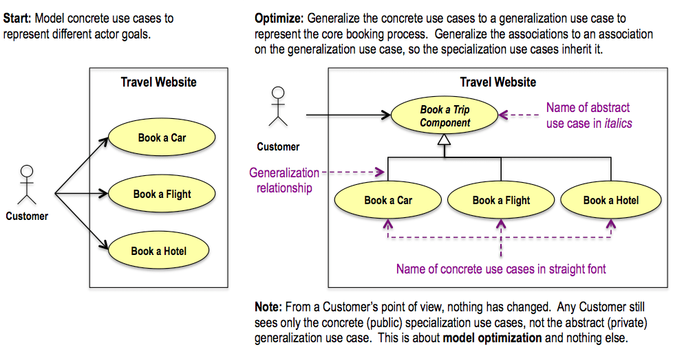
Imagine producing a use case model for a travel website and finding out that the concrete use cases Book a Car, Book a Flight and Book a Hotel are all based on one core booking process and only differ in certain details.  How can you define the core booking process once and address the unique details for each concrete use case?  

By using use case generalization, of course!  See next diagram (i) (ii).
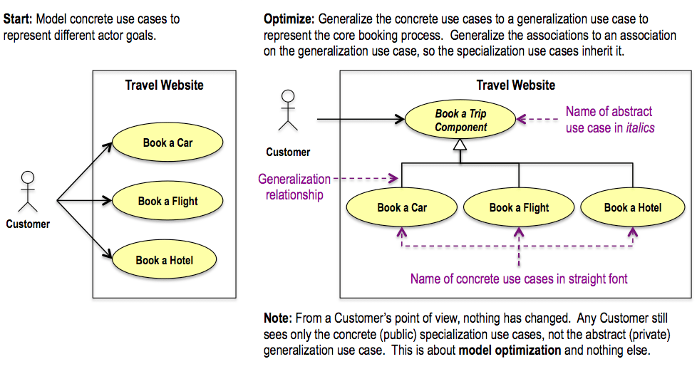
MVGAug6th-1

Use case generalization (and specialization) results in a use case hierarchy.

What a use case hierarchy means

Because we’re generalizing three already existing concrete use cases, the resulting generalization use case is ‘completely partitioned’ (entirely subdivided into sub use cases) and therefore abstract (no use case instances can be created in it).

As with any generalization, type correspondence between the sub and super use cases is a must.  The statements ‘Book a Car is a type of Book a Trip Component’, ‘Book a Flight is a type of Book a Trip Component’ and ‘Book a Hotel is a type of Book a Trip Component’ are all true, so the use case hierarchy is appropriate.

When a concrete use case has a generalization relationship with a generalization use case, it means that at run time the generalization use case’s specification and the concrete use case’s specification are combined into a single use case specification that governs the behavior of each use case instance in the concrete use case.

  • The behavior of a concrete Book a Car use case instance is governed by the combined use case specifications of the Book a Trip Component and Book a Car use cases.
  • There will never be a Book a Trip Component use case instance.

The use case specifications

The generalization use case’s specification:

  • Defines the initiating actor, provided this is common to all of the specialization use cases.
  • Defines the supporting actor(s) common to all of the specialization use cases. 
  • Defines the steps that are common to all of the specialization use cases.
  • May define default steps that apply to some but not all of the specialization use cases (*).
  • May define empty placeholders for steps that are to be defined by one or more of the specialization use cases (**).

A specialization use case’s specification:

  • Defines the initiating actor, provided this is not defined by the generalization use case specification.
  • Defines any supporting actor(s) needed by the specialization use case and not defined by the generalization use case specification.
  • May override default steps of the generalization use case’s specification, by defining its own version of those steps (*).
  • May fill in empty placeholders of the generalization use case’s specification, by defining its own steps for those placeholders (**).
  • May delete steps of the generalization use case’s specification.
  • May add its own steps, which aren’t in any way anticipated in the generalization use case’s specification (***).

(*)  Similar to the object-oriented example’s ‘method override’ pattern in [2].
(**)  Similar to the object-oriented example’s ‘method deferral’ pattern in [2].
(***)  Similar to the object-oriented example’s ‘operation addition’ pattern in [2].

In the end, both specifications must be written so that when they’re combined, the result represents the complete specification for the specialization use case.

The two specifications are always “textually combined”, similar to the way some included use case specifications are “textually included” in a base use case specification, as outlined in [3] and [4].

Object-oriented use case implementation

Specifying use case steps this way foreshadows an object-oriented implementation of the use cases involved, where the steps of the use cases map to operations on underlying classes. 

  • Just like the steps are defined for generalization and specialization use cases, the operations can be defined on generalization and specialization classes, as illustrated in the object-oriented example in [2].

GENERALIZING SYSTEMS

What is a system, again?

According to 16.3.2 (iii) in [1], a UseCase has:

  1. An ‘owning classifier’.  This is the ‘namespace’ of which the UseCase is an ‘owned member’.  It is the unique location in a model where the UseCase is defined (iv).
  2. Zero or more ‘subjects’.  These are the Classifiers to which the UseCase applies (for a given ‘subject’, the UseCase “specifies some behavior […] that the subject can perform”).

Section 16.3.2 in [1] states that “the owning classifier typically represents the subject to which the owned use cases apply”, but adds that “this is not necessarily the case.”

  • Since a Classifier (and therefore, a UseCase) can be a PackageableElement, and a PackageableElement is owned directly by a Package, a UseCase’s ‘owning classifier’ can be a Package.
  • Obviously, a UseCase doesn’t represent behavior that a Package can perform, because a Package is merely “used to group [model] elements, and provides a namespace for the grouped [model] elements.”

So, if and when a UseCase’s ‘owning classifier’ is a Package, the UseCase’s ‘subject’ defines the system (or its ‘subjects’ define the systems) to which the UseCase applies.  But why can there be multiple subjects?

  • Although [1] doesn’t seem to state it outright, I suspect this is meant to support UseCase reuse.

In any event, a UseCase “specifies some behavior […] that [a system] can perform”, where ‘system’ is either the UseCase’s ‘owning classifier’ or one of the UseCase’s ‘subjects’ (if the ‘owning classifier’ is a Package).  The article’s remainder uses the generalized term ‘system’, which covers both alternatives.

Section basis

The contents of this section are based on the following assertions.

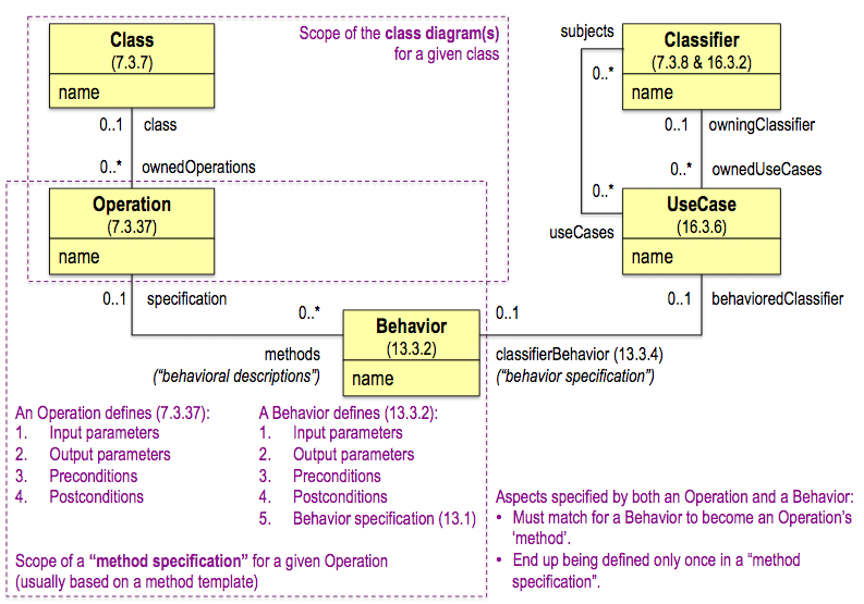
  • A use case is to a ‘system‘ what an operation is to a class.
  • A ‘classifier behavior’ is to a use case what a ‘method’ is to an operation.

UML metamodel summary

These statements are based on the next diagram, which summarizes the classes and associations from [1] that are essential to these points.  The diagram shows how the pattern of a Classifier (‘system’) and its UseCases mirrors the pattern of a Class and its Operations, and how the pattern of a UseCase and its ‘classifier behavior’ mirrors the pattern of an Operation and its ‘method’.
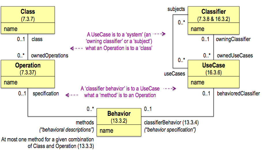
MVGAug6th-2

Classifier diagram

Because of the above, and using the default Classifier notation (7.3.8), we can show Classifiers (‘systems’) and their UseCases in a “classifier diagram” like the one below, similar to how we can show Classes and their Operations in a class diagram like the one in [2].

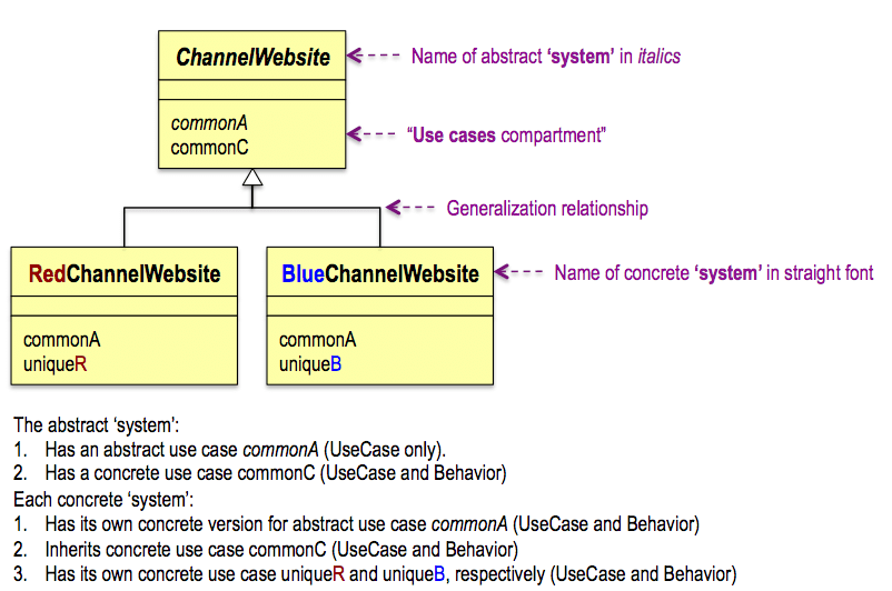
Imagine a consumer electronics retailer with two branded distribution channels, and a website for each channel.  In the next diagram, the abstract channel website system represents what the concrete channel website systems have in common (v).
MVGAug6th-3

Justification

I don’t recall reading about a system hierarchy elsewhere, but it strikes me as valid, for the following reasons.

  1. A UseCase’s ‘system’ is a Classifier, and as such is concrete or abstract (7.3.8).
  2. Since they are Classifiers, ‘systems’ can be arranged into a hierarchy, using generalization relationships (7.3.8).
  3. Since a UseCase is to a ‘system’ what an Operation is to a Class, a UseCase can be shown in the “use cases compartment” of a ‘system’, similar to how an Operation is shown in the operations compartment of a Class (7.3.8).
  4. Because a UseCase is also a type of RedefinableElement “defined in the context of a classifier” (7.3.47), it can be “redefined more specifically or differently in the context of another classifier that specializes (directly or indirectly) the context classifier.”  In other words, a UseCase of a super ‘system’ can be redefined by a sub ‘system’, similar to how an Operation (also a type of RedefinableElement) of a super Class can be redefined by a sub Class.

Type correspondence

As is the case for a class hierarchy, ensuring type correspondence is a must for a system hierarchy.

  • In this case, the statements ‘the Red Channel Website is a type of Channel Website’ and ‘the Blue Channel Website is a type of Channel Website’ are true, so the system hierarchy is appropriate.

Class diagram and method specification

Based on the earlier class diagram, the diagram below illustrates the scope of:

  • A class diagram.
  • What I know as a “method specification”.

MVGAug6th-4

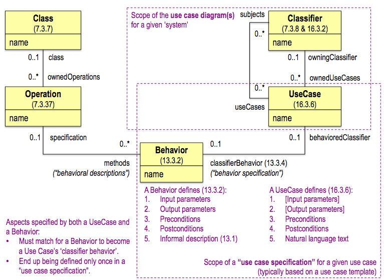
Use case diagram and use case specification

Along similar lines, the following diagram illustrates the scope of:

  • A use case diagram.
  • What I habitually refer to as a “use case specification”.
MVGAug6th-5

Note:

  • Since the earlier diagram doesn’t include actors, neither does this one; however, actors are part of both scopes, as applicable.
  • While [1] specifies that both an Operation and a Behavior specify preconditions and postconditions, it makes no such statement about a UseCase, which is why these conditions are in square brackets in the above diagram. 
  • However, given this comparison of a UseCase to an Operation, it stands to reason to expect a UseCase to specify preconditions and postconditions as well. 
  • In fact, this is a must for a UseCase whose system doesn’t provide a Behavior for it, but defers this to its sub systems (like the object-oriented example’s ‘method deferral’ pattern in [2]). 
  • See also the discussion on contravariance (of superclass and subclass preconditions) and covariance (of superclass and subclass postconditions) in chapter 11 of [5].

Use case parameters

Using the use case stereotypes I mentioned in earlier articles, use cases and parameters relate as follows.

  • A <> use case (short for ‘application function’; initiated by a person) typically has no parameters, because data is exchanged between user and system as a use case execution unfolds.
  • A <> use case (initiated by an electronic entity) typically has input and output parameters, because that’s the nature of a service.  This kind of use case is most like an operation of a class.
  • A <> use case (short for ‘scheduled process’; initiated by a schedule or time) typically has no parameters, because it knows by design where to get its input and where to put its output.

Use case reuse

A system hierarchy enables use case reuse within the hierarchy, where there is type correspondence between the systems.  Assigning a use case to multiple ‘subjects’ accommodates use case reuse without a system hierarchy, so there isn’t necessarily type correspondence between the systems.

Use case polymorphism

Both reuse approaches contribute to polymorphism, where different systems can respond to the same kind of message requesting the execution of a certain use case. 

Scope of polymorphism

The scope of polymorphism for a given use case is the set of systems to which the use case applies (directly or indirectly) and can be one of the following.

  • When using a system hierarchy, the top-level system that defines a certain use case and the lower-level systems that inherit it, form what [5] calls a ‘cone’ of polymorphism, because the scope of polymorphism is (a branch of) the inverted tree structure of a system hierarchy, which is shaped like a cone.
  • When assigning a use case to multiple ‘subjects’, those systems end up forming what [5] calls a ‘ragged’ scope of polymorphism, because the scope doesn’t necessarily correspond to (a branch of) the inverted tree structure of a system hierarchy, and therefore doesn’t necessarily form a cone shape.

Implementation considerations

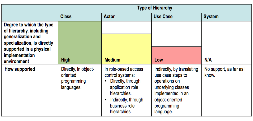
The table below summarizes for the hierarchy types discussed in this article to what degree they’re directly supported in the physical (technology-specific) domain.

Since these constraints do not apply to the logical (technology-neutral) domain to which use case models belong, we can use actor, use case and system generalization in use case models without reservation.
MVGAug6th-6

In conclusion

Actor, use case and system generalization (and specialization) are special tools we can add to our use case modeling toolbox.  We may not use them all that often (they are listed in most-to-least-likely-to-use order), but it’s good to know they’re there, just in case we encounter those special circumstances where they’re just what we need to get the job done right.

Don’t forget to leave your comments below.


Notes

(i)  To convey the fundamentals as clearly as possible, the example is purposely kept simple and excludes additional trip components (e.g., a cruise), trip component bundles (e.g., flight + hotel), and the use of external systems (supporting actors).

(ii)  Associating the initiating actor with an abstract use case is notational shorthand for associating the initiating actor with each of the concrete use cases instead.  As such, it upholds the rule that a concrete use case is a use case that has an initiating actor.  See also the inherited association in the object-oriented example in [2].

(iii)  Throughout the article, 2- or 3-part numbers refer to sections in [1] (e.g., 13.3.2) and UML role names are enclosed in single quotes (e.g., ‘classifier behavior’).

(iv)  The ownership association between Classifier and UseCase is a specialization of the ownership association between Namespace (‘namespace’) and NamedElement (‘owned member’).  While ‘owned member’ is specialized to ‘owned use case’, no specialization for ‘namespace’ is given.  This article uses ‘owning classifier’ as that specialization, which [1] uses throughout the text but not in the formal model.

(v)  A “classifier diagram” introduces a clash of terms, because in such a diagram:

  • An abstract use case is a UseCase for which the system doesn’t provide a Behavior, not a UseCase that cannot be instantiated.
  • A concrete use case is a UseCase for which the system does provide a Behavior, not a UseCase that can be instantiated.

To avoid this clash, alternative terms in a “classifier diagram” could be:

  • An ‘abstract as operation’ UseCase.
  • A ‘concrete as operation’ UseCase.

References

[1] Object Management Group (OMG), OMG Unified Modeling LanguageTM(OMG UML), Superstructure, Version 2.4.1.

[2] Willem Van Galen, Generalization and Use Case Models, Part 1, 12 August 2013, http://www.batimes.com/articles/generalization-and-use-case-models-part-1.html

[3] Willem Van Galen, Putting The Inclusion Use Case In Focus, 21 August 2012, http://www.batimes.com/articles/putting-the-inclusion-use-case-in-focus.html

[4] Willem Van Galen, The Include Relationship’s Other Use, 18 June 2013, http://www.batimes.com/articles/the-include-relationships-other-use.html

[5] Meilir Page-Jones, Fundamentals of Object-Oriented Design in UML, 4th Printing, September 2000, Addison-Wesley.
 

Generalization and Use Case Models, Part 1

INTRODUCTION

Starting with an object-oriented example to set the stage, this article explores generalization (and specialization) in use case modeling. Part one outlines key concepts and addresses generalization of use case actors. Part two covers generalization of two additional use case model elements.

SETTING THE STAGE

The best way to promote a common understanding of generalization is through a simple object-oriented example, especially since use case models are founded on object-oriented principles (i). Most of the concepts encountered in the example trace back to [1] and [2], which strike me as highly informative books.

An object-oriented example

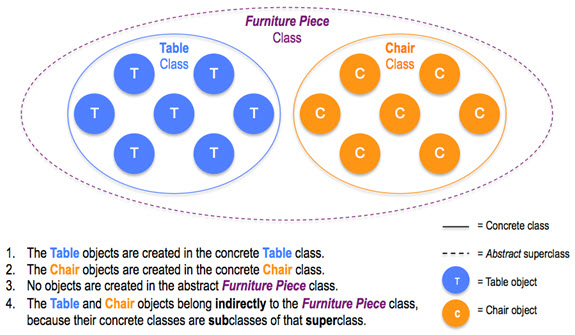
Imagine an object-oriented inventory system for an organization’s tables and chairs. In the real world, each table and each chair is a physical object. In the electronic world of the inventory system, each physical table is represented as an electronic object of type Table and each physical chair is represented as an electronic object of type Chair, so that:

  • Each object’s type indicates what the object is in and of itself (independent of any context), for its entire existence (the type doesn’t change during the object’s lifetime).
  • An object’s type corresponds to the concrete class in which it is created (ii), so that an object of type Table is created in the concrete class Table and an object of type Chair is created in the concrete class Chair.

The Table and Chair classes are defined beforehand and specify the kinds of characteristics (e.g., particular attributes and associations) for which an object created in the class has individual characteristics (e.g., specific attribute values and links). For example, a Chair object has a True or False value for the Chair class’s hasArmRests attribute.

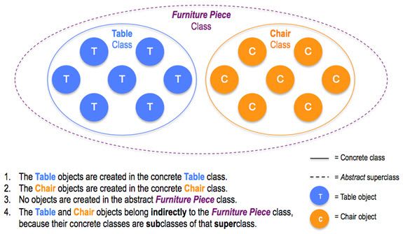
In defining these concrete classes, we may notice that they have certain kinds of characteristics in common (e.g., they both have the ‘color’ attribute). This is a clue that we can generalize these classes to a superclass, like Furniture Piece, to represent what tables and chairs have in common.

  • Since each object that belongs to the Furniture Piece class is either a Table or a Chair, the Furniture Piece class is said to be abstract, to indicate that it cannot be instantiated (there will be no objects of type Furniture Piece).
  • Another way to express this is that the Furniture Piece class is ‘completely partitioned’ (it is completely subdivided into subclasses).

Furniture Piece represents a ‘generalization’ of (the objects in) its subclasses, as depicted in the following diagram.

VanGalenAug12 01

Class hierarchies

Generalizing classes creates a class hierarchy. In this example, it starts with a flat structure of two concrete classes that reflect what their objects are in and of themselves, which is then expanded into a hierarchy by adding an abstract superclass that represents what objects in the two subclasses have in common.

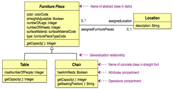
The class hierarchy in the diagram above is represented below as a class diagram, expanded with some attributes (iii), an association, and some operations (see later).

VanGalenAug12 02

Inheritance

A key feature of a class hierarchy is inheritance, in which kinds of characteristics defined for a superclass are inherited by its subclasses.

Inheritance is a class construct, not an instance one.

  • This means that, for example, the Table and Chair classes inherit the color attribute from the Furniture Piece class, such that each Table and Chair object must be assigned a value for the color attribute at the time of the object’s creation.
  • It does not mean that each Table and Chair object inherits its particular color (a color attribute value) from a corresponding Furniture Piece object, because there are only Table and Chair objects, no Furniture Piece objects.

Likewise, the Table and Chair classes inherit the association with the Location class from the Furniture Piece class, such that each Table and Chair object may have a link to an ‘assigned location’.

Specialization

A class hierarchy can also result from specialization. This means introducing a subclass, and representing how it differs from its superclass by defining kinds of characteristics that apply to the subclass but not to the superclass (iv).

  • To a superclass, a subclass is a ‘specialization’ of the superclass.
  • To two or more subclasses, a shared superclass is their ‘generalization’ (v).

In the earlier class diagram, Table and Chair are specializations of Furniture Piece, where Table has the maxNumberOfPeople attribute (but Furniture Piece doesn’t) and Chair has the hasArmRests attribute and the getSeatingPosition operation (but Furniture Piece doesn’t).

The following three sections describe additional examples of specialization.

Deferring methods to subclasses

Apart from inheriting attributes and an association, Table and Chair also inherit the getCapacity operation (vi). An operation on a class represents that an object in the class is capable of a named behavior, in this case, getting its capacity.

  • Capacity represents the number of people the corresponding physical object can accommodate.
  • A Table’s capacity is indicated by the maximum number of people that can sit around it, while a chair’s capacity is always equal to one.

The Furniture Piece’s operation is shown in italics to indicate that it’s abstract. This means that Furniture Piece doesn’t provide a method for this operation but leaves it up to its subclasses to do so (vii). In contrast, Table and Chair show the operation in straight font to convey that it’s concrete. This means that each subclass provides its own method for the operation.

  • Thus, when a Table object is asked to perform the operation, the Table class’s method is to return the Table object’s value for the maxNumberOfPeople attribute, and when a Chair object is asked to perform the operation, the Chair class’s method for this operation is to return 1.

So, providing a method for the superclass’s operation is deferred to the subclasses.

Overriding a method

An alternative pattern for modeling the getCapacity methods is as follows.

  • Furniture Piece’s getCapacity operation is concrete and its method is to return 1 (i.e., this is the default method).
  • Chair inherits the method from Furniture Piece, but Table defines its own method, which is to return a Table object’s value for the maxNumberOfPeople attribute.

Thus, Table’s own method overrides Furniture Piece’s default method.

Adding an operation and its method

Chair has an operation over and above the one it inherits.

  • The getSeatingPosition operation returns “in” or “on” for a given Chair object.
  • The corresponding method gets the Chair’s hasArmRests attribute value, and returns “in” or “on” based on whether this value is True or False, respectively.

The added operation helps to define Chair as a specialization of Furniture Piece.

Type and class

In philosophy, there is a difference between a type (which represents a certain concept, like chair) and a class (which is a collection of objects, such as tables and/or chairs).

In class diagrams, these two aspects are combined, such that a class represents both a concept (through the kinds of characteristics that characterize it) and a collection (of objects that have individual characteristics for those kinds of characteristics).

Even so, there is still a linguistic distinction, because an object ‘is of’ a certain type but ‘belongs to’ (is a member of) a class. At minimum, an object that is of a certain type belongs to the concrete class in which it is created; if that class has any superclasses, the object belongs to those as well, albeit indirectly.

Type correspondence

A key measure of the correctness of a class hierarchy is type correspondence. This means that the statement ‘ is a type of ’ must be true for each combination of subclass and superclass (representing the subtype and the supertype, respectively, keeping in mind that a class represents both a type and a collection).

  • For example, ‘a Table is a type of Furniture Piece’ and ‘a Chair is a type of Furniture Piece’.

Let’s now turn to generalization (and specialization) in use case modeling. 

GENERALIZING ACTORS

Why actors can be generalized

In [3], Actor is a subclass of BehavioredClassifier, which is a subclass of Classifier. Because generalization is a feature of Classifier, Actor inherits this feature from that class. In other words, actors can be arranged in an actor hierarchy.

An example

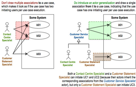
A concrete use case has one and only one initiating actor (viii), but what if some of a system’s use cases can be initiated by users of different kinds, such as Contact Centre Specialists and Customer Statement Specialists? Actor generalization solves that problem, as illustrated in the following diagram.

VanGalenAug12 03

Actor generalization (and specialization) creates an actor hierarchy.

What an actor means

The earlier object-oriented example deals with electronic objects internal to a system, each of which comes into existence by being created in a concrete class. In contrast, the notion that actor instances are created in concrete actors doesn’t apply, because:

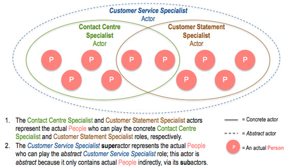
  • An actor represents actual entities that can use a system (e.g., actual people, actual systems, actual functions), which already exist in their own right.
  • An actor represents a role some entity may play, not what the entity is in and of itself.

When an actor is concrete, it means that entities are assigned to it, not that they are created in it.

Two patterns

In fact, we need to be aware of two modeling patterns, for which I use the following terms and definitions.

  • Classification: arranging entities in classes based on what the entities are in and of themselves, such that an entity belongs to one and only one concrete class that reflects the entity’s type, and belongs to that class for its entire existence (ix).
  • Categorization: assigning entities of one or more types to categories, based on point-in-time rules, judgment or preference, such that an entity may belong to multiple categories at once, and may belong to a category for part(s) of its existence.

Thus, the earlier class hierarchy reflects classification, while the above actor hierarchy represents categorization. The next diagram shows the latter (x).

VanGalenAug12 04

Like the Furniture Piece class in the object-oriented example, the Customer Service Specialist actor is abstract, because it is completely partitioned (i.e., completely subdivided into subactors).

Unlike the Furniture Piece class, the Customer Service Specialist actor is not ‘disjoint’, but ‘overlapping’ (as [3] calls it), because a given person can in principle belong to multiple subactors at once (a clue we’re dealing with categorization, not classification).

Type correspondence

As for a class hierarchy, ensuring type correspondence is a must for an actor hierarchy, albeit that here the types are strictly the actor names themselves, rather than the types (conceptual or otherwise) of actual users (e.g., Person).

  • In this case, ‘a Contact Centre Specialist is a type of Customer Service Specialist’ and ‘a Customer Statement Specialist is a type of Customer Service Specialist’ are true, so the actor hierarchy is appropriate.

Actor hierarchy antipattern

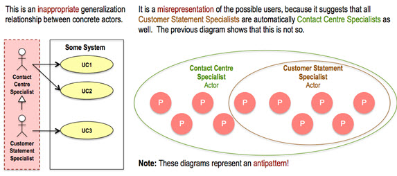
Sometimes, use case texts advocate adding a generalization relationship between two concrete actors. This is only appropriate when any and all members of the subactor are always members of the superactor as well. If not, this kind of actor hierarchy is a misrepresentation, as the following diagram illustrates.

VanGalenAug12 05

Below are two more examples of an actor hierarchy.

VanGalenAug12 06

To avoid an inappropriate actor hierarchy, add an abstract superactor as shown earlier, and let the overlapping nature of the concrete subactors handle the scenario where a person can belong to both subactors, through individual assignment.

NOTES
(i) To keep it simple, the example only deals with one abstract superclass and two concrete subclasses.

(ii) Some refer to instantiating an object, which seems inappropriate. Instantiation means representing a concept (e.g., chair) by an instance (e.g., a chair), so it’s the concept that is instantiated, not the instance. In object-oriented terms, a concrete class can be instantiated (can have objects created in it), but an abstract class can’t.

(iii) While most attributes have a data type like Boolean, Integer or String, the data type of each of the remaining attributes refers to an enumeration, which is a list of the attribute’s allowed values.

(iv) Specialization isn’t necessarily the opposite of generalization. You can’t generalize a single class to a superclass, but you can specialize a class to a single subclass. The latter means that:

  • The class is concrete to begin with (objects are or can be created in it).
  • A subset of the class’s objects are moved to the subclass (i.e., they’re deleted from the class and created in the subclass with a new type that equals the name of the subclass).
  • The class retains its remaining objects (whose type equals the name of the class).
  • In other words, the class is not completely partitioned.

(v) This article avoids ‘generalized’ and ‘specialized’ as qualifying terms, because they’re ambiguous (e.g., does ‘generalized’ apply to the two or more classes being generalized, or to the class that represents the generalization?); the unambiguous qualifiers ‘super’ and ‘sub’, as well as ‘generalization’ and ‘specialization’, are used instead.

(vi) Class operation: to be performed by a class as a whole (e.g., create an instance). Instance operation: to be performed by a specific object in a class. In this article, each operation is an instance operation.

(vii) Method: a representation of how a class or an object will respond when asked to perform a given operation.

(viii) The examples in 16.3.6 of [3] where “more than one actor instance is involved in initiating the use case” can be represented more simply as one initiating actor and one supporting actor.

(ix) There are entities that change types during their existence (e.g., a caterpillar changes to a butterfly), but such type changes are outside the scope of this article, because they usually don’t have to be dealt with in a typical system.

(x) See 16.3.1 in [3], “Actors may represent […] multiple different instances.”

Don’t forget to leave your comments below.

REFERENCES

[1] Meilir Page-Jones, Fundamentals of Object-Oriented Design in UML, 4th Printing, September 2000, Addison-Wesley.
[2] Bruce F. Webster, Pitfalls of Object-Oriented Development: A Guide for the Wary and the Enthusiastic, 1995, M&T Books.

[3] Object Management Group (OMG), OMG Unified Modeling LanguageTM (OMG UML), Superstructure, Version 2.4.1.