
Tag: Planning

A Real-World Example of the State Transition Diagram

Whenever a workflow of some kind is being converted to an electronic process, you’re going to be looking at creating a status-driven process. That’s because the object passing through the workflow needs to receive status changes to indicate that the previous step is completed, and to trigger the next step of the process. Recently I was involved in a project converting a thesis submission process from a paper-based process to an electronic process and it serves to illustrate the usefulness of the State Transition Diagram for this type of project.

In this example I used the Bizagi Process Modeler to create my State Transition Diagram. I prefer it over the other tools I use because it’s free, the diagrams are more aesthetically pleasing than the other tools I’ve used, and it is quick and easy to use.

Bennett Dec11 Img01To give you some background about the project that the State Transition Diagram presented below is based on, the submission of Master’s and Ph.D. theses in my institution is not overly complicated, but there are many different forms that must be completed by a variety of people, including students, administrative staff, and faculty. I needed an easier way of explaining all the steps of the process and what forms were being released at each step. Enter the State Transition Diagram.

Something else we had to make a decision on with this project was where to start the electronic process. The thesis submission process is lengthy, and we had to decide whether to include the part of the process – before it is officially deposited at the Graduate Studies office – when the thesis is still under development. To reduce the scope of the project, we decided to start the electronic process after the thesis has been developed and the student is ready to officially submit it to Graduate Studies.

Click image to view larger.
Bennett Dec11 Img02

This diagram demonstrates the status progression of the submitted thesis. Starting from the left, we see the first status is “Pre-Upload”. This is before the thesis is uploaded by the student. The circle following that status is the “Thesis Uploaded” event. Any circles like this one that have a double border around it are known as events. This first event indicates that the student has uploaded their thesis via the new electronic process. From this event we see a dotted line leading up to a gray rectangle, known as an annotation. The items listed in this rectangle indicate the forms that the student must complete as they upload their thesis. Once this event occurs, the status of the thesis becomes “Thesis Package Received”, which triggers the release of the Thesis Defence Authorization Forms. These are forms that go to the members of the defence committee who must decide whether the thesis is suitable to defend, hence the decision diamond that follows this status: “Defence Authorized?”. If the decision is no, the status of the thesis becomes “Defence Denied”. If yes, we next see the “Notice of Defence Approved” event. This is where a notice is posted in some locations around the university listing the members of the defence committee, and the date, time, and location of the defence. Once this event occurs, the status of the thesis becomes “Ready for Defence”, and from this status we see another annotation leading upwards listing some more forms that are released with this status change. Following this status is the “Defence” event. This is where the student defends their thesis before the defence committee. At the defence the committee will determine whether revisions are required or not, and thus we see another decision diamond for “Revisions?”. If the decision is no, the status proceeds to “Thesis Accepted”. If yes, the status becomes “Requires Major/Minor Revisions”, and in the annotation above this status we see the Thesis Revisions Approval Form is released. Following the “Requires Major/Minor Revisions” status is the “Revisions Uploaded” event. This is where the student has uploaded their modified thesis according to the revisions that were provided to the student at the defence. At this point the decision must be made as to whether to accept the revisions or not, and so we see the decision diamond “Accepted?”. If no, the flow goes back to the “Requires Major/Minor Revisions” status. If yes, it proceeds to the “Thesis Accepted” status. Going down from this status is another annotation showing the final forms that the student must complete before the thesis is electronically packaged and sent to the Library for publication. That’s why the next event we see is “Thesis is sent to the Library”, followed by the final status “Transferred to Library”. This is the end of the electronic thesis submission process.

Explaining this workflow to my stakeholders with the help of this State Transition Diagram that they could follow along with was much easier and was more meaningful than reading just a written explanation or explaining it verbally. It may not be a useful tool in all situations, but for workflows, I find it indispensable.

Don’t forget to leave your comments below.

Use Case Goals, Scenarios and Flows

VanGalenNov13 IMG01Introduction

This article is inspired by two more of Alistair Cockburn’s “gold nuggets” found in his book Writing Effective Use Cases [1].  The first nugget is the idea of a goals hierarchy, which represents, among other things, how the goals of a system’s use cases are derived from and trace back to larger goals of the system’s users.  The second nugget is his “striped trousers” explanation of use case scenarios, which are sequences of use case steps that represent different paths through a use case in pursuit of the use case’s goal.  This article also demonstrates a convention for organizing a use case’s steps based on the established approach of writing use case steps nonredundantly by using flows of different kinds.  It even introduces a new kind of flow and advocates its use over that of the extension use case in specific circumstances.

Goal hierarchies

Cockburn provides a mental model of how people and organizations function on the basis of a hierarchy of goals, where each goal, but at its highest-level belongs to one or more higher-level goals and each goal, but at its lowest-level, breaks down into multiple lower-level goals.

  • Moving down the hierarchy answers “How?” to show how a certain goal can be achieved.
  • Moving up the hierarchy answers “Why?” and provides a rationale for why a certain goal exists.

These goals are pursued by different role players (people), organizations (groups of people) and systems (automated resources) inside and outside an organization.

Use case goals

A use case arises when a person (or a system) with an overall goal needs to interact with a supporting system in order to achieve a mini goal as a step towards reaching the overall goal.  The use case represents the supporting system’s ability to deliver the user’s mini goal, and this it the use case’s overall goal.  This can be reflected no more clearly than by naming the use case after that goal.  The use case’s specification details how the use case’s overall goal is broken down into its own mini goals, represented by steps and groups of steps.

Thus, the user’s overall goal, the user’s mini goal/use case’s overall goal, and the use case’s mini goals are seamlessly incorporated into an organization’s goals hierarchy.

The beauty of this perspective is that:

  • System use cases arise from and trace back to the goals of a system’s users, rather than a use case modeler’s imagination.
  • The idea of a goals hierarchy that integrates the goals of groups of people with the goals of people, the goals of people with the goals of supporting systems, and the goals of supporting systems with the goals of their internal steps provides a single paradigm for how an organization functions across all of its levels in both manual and automated ways.

Use case scenarios

A use case scenario is a sequence of steps that represents a single use case execution (a scenario is a possible path through a use case specification).

Cockburn presents a diagram (Figure 2.2 in [1]), whose originality and quirkiness are only exceeded by its effectiveness. He calls it the “striped trousers” view of a use case and its scenarios. In it:

  • The belt represents “the [use case] goal that holds all the scenarios together.”
  • One leg “is for the scenarios that end in success.”
  • The other leg “is for the scenarios that end in failure.”
  • “Each stripe corresponds to a scenario.”
  • “The first stripe on the success leg [is] the main success scenario.”
  • “The leg’s remaining stripes are [all] other scenarios that ultimately end in success – some through alternate success paths and some after recovering from an intermediate failure.”
  • The stripes on the failure leg are scenarios that encounter one or more intermediate failures, possibly recover from some, but always fail eventually.

As Cockburn says, this model “is useful for keeping in mind that every use case has two exits, that the [initiating] actor’s goal binds all the scenarios, and that every scenario is a simple description of the [use case] succeeding or failing.”

This strikes me as one of the greatest contributions to use case modeling.

Use case flows

Cockburn points out, “We won’t actually write every scenario separately from top to bottom.  That is a poor strategy because it is tedious, redundant, and hard to maintain.”

Instead, a use case can be written nonredundantly, starting with an unconditional main flow that is subsequently enhanced with conditional additional flows of different kinds, where a flow is a sequence of steps.  The main flow equates to “the main success scenario” and each additional flow represents a portion of one or more of the remaining scenarios.

The UML doesn’t deal with flows.  Cockburn only refers to “the main success scenario” (main flow) and “extensions” (additional flows).  Refining this view, the following sections present five different kinds of flow by providing a definition, diagram and simplified example for each.  The purpose of the examples is to illustrate a clear, consistent and scalable writing convention for representing a use case’s structure (they’re not meant as full-fledged use case specifications).

The main flow

Definition: An unconditional set of steps that describe how the use case goal can be achieved and all related stakeholder interests can be satisfied.  Each step is essential to achieving the use case goal (no step can be skipped), and each step succeeds.VanGalenNov13 IMG02

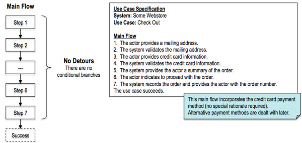
Cockburn calls this “the main success scenario,” and others use the terms “the happy path,” “the basic flow” and “the normal course of events.”  My preference is for “the main flow” because it’s short and ties in well with the names of the other kinds of flow.

The next four sections outline what collectively can be called additional flows.

An alternative flow

Definition: A conditional set of steps that are an alternative to one or more steps in another flow (the alternative flow is performed instead of the other step or steps), after which the use case continues to pursue its goal.
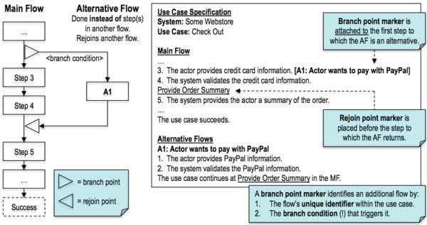
VanGalenNov13 IMG03

A recovery flow

Definition: A conditional set of steps that are a response to the failure of a step in another flow (the recovery flow is performed after the other step), after which the use case continues to pursue its goal.
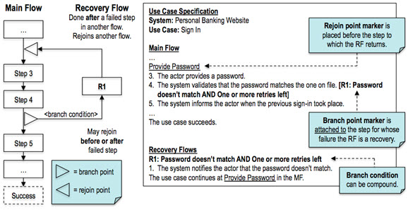
VanGalenNov13 IMG06

An exception flow

Definition: A conditional set of steps that are a response to the failure of a step in another flow (the exception flow is performed after the other step), after which the use case abandons the pursuit of its goal.
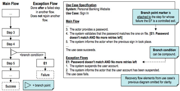
VanGalenNov13 IMG07

An option flow

Definition: A conditional set of steps that represent a nonessential option available between two steps in another flow (the option flow is performed between the two steps), after which the use case continues with the second of those steps.VanGalenNov13 IMG08

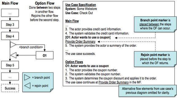
The option flow’s main purpose is to represent behavior that is nonessential to achieving the use case goal (the behavior can be skipped) but that still contributes to that goal in some way (the behavior only has meaning in the context of that goal).

An “option” is like an optional feature in a new car (e.g., sun roof).  Choosing the option contributes to the goal (order a car), but you can order a car with or without the option (a sun roof is not essential).  Continuing the analogy for another term in this article, a car’s possible engine sizes beyond the standard size are “alternatives” to the standard size (but having an engine of some size is essential).

On point markers

Before taking a closer look at the option flow, here are some comments about branch point markers and rejoin point markers.

Advantages.

  • There is no need to reference actual step numbers (the convention used in [1]); these change when steps are added, deleted or reordered, and if we forget to update their references then the use case becomes corrupted.
  • A flow’s branch points and rejoin points are immediately obvious from the flow’s own description, rather than only from the descriptions of the additional flows that branch off the flow (the convention used in [1]).

Placement of branch point markers. 

  • As the examples show, a branch point marker for an alternative, recovery or exception flow is attached to a main flow step, rather than placed before or after the step; this keeps markers from visually dominating the main flow.
  • This doesn’t apply to the option flow, which by its very nature occurs between two steps.

More on the option flow

What an option flow is not

An option flow is not:

  • Part of the main flow, because an option flow is conditional and nonessential to achieving the use case goal, which is the very opposite of the main flow.
  • An alternative flow, because an option flow isn’t an alternative to a step or steps.
  • A recovery flow, because an option flow is not a response to a failed step.
  • An exception flow, because an option flow is not a response to a failed step and doesn’t mean the use case failed.

Use an extension use case instead?

You may wonder whether nonessential goal-related behavior can be represented as an extension use case instead, given the UML’s extension use case description in [2].  To help answer that, the next table lists key UML statements about the extension use case and their applicability to the option flow.VanGalenNov13 IMG09

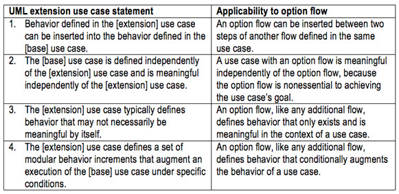
At first blush, the above, and in particular its first two statements, suggests it’s reasonable to represent nonessential goal-related behavior as an extension use case.  However, for a conclusive answer, we turn to the extension use case interpretation outlined in [3].

When to use an option flow and when to use an extension use case

Based on [3], the next table repeats when behavior can be modeled as an extension use case and gives answers for the behavior of the earlier Coupon option flow.VanGalenNov13 IMG10

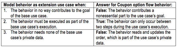
Regarding the False answers for the Coupon option flow behavior:

  1. The third answer is soft: the order could be declared public data, which would change the answer to True.
  2. The first answer is hard: it is and remains a fact that the Coupon option flow behavior contributes to the use case goal, so the answer is always False.

This leads to the following conclusion:

  • Nonessential behavior that in some way contributes to the use case goal must always be modeled as an option flow and never as an extension use case.
  • Nonessential behavior that doesn’t contribute to the use case goal in any way may be modeled as an extension use case (when all three questions are answered with True) or as an option flow (when the third question is answered with False).

Other differences between the option flow and the extension use case

Key to the above conclusion is whether nonessential behavior contributes in some way to a use case’s goal or not.  When it does, using an option flow has undeniable advantages over even thinking about using an extension use case.  These aren’t considered in [3] but do reinforce the above conclusion, which is based on [3], as shown in the following table.VanGalenNov13 IMG11

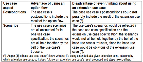
Thus, the extension use case turns out to be an inappropriate choice for modeling nonessential goal-related behavior; in contrast, the option flow is ideal for this.

Benefits of using the option flow

Ease of producing use case models: 

  • Only need to model one use case for a given goal, not two or more (prevents “use case bloat”).
  • No need to use the special extension use case construct, its involved UML diagramming convention and a custom writing convention; in contrast, writing an option flow and its branch and rejoin points follows the convention used for all additional flows.

Ease of consuming use case models:

  • It’s easier to consume one use case for a given goal than two or more (most consumers will agree with this).
  • A use case’s postconditions and scenarios are all in one place (great for all consumers, but especially for testers).

In conclusion

It is my hope that this article will contribute to crisp, clear and consistent use case models (including diagrams and specifications), and will benefit their producers and consumers, as well as the organizational benefit of their employers.

References

[1] Alistair Cockburn, Writing Effective Use Cases, 12th Printing, November 2004.

[2] Object Management Group (OMG), OMG Unified Modeling LanguageTM (OMG UML), Superstructure, Version 2.4.1, Section 16.3.3, Description.

[3] Willem Van Galen, Excavating the extension use case, 10 July 2012,  (Part 1) and 24 July 2012, (Part 2).

Don’t forget to leave your comments below.

What Should I Do If My Agile Team Can’t Be Co-Located?

One criterion for team selection is member co-location. Whether working in nearby cubicles or in an open space, short distances between members contribute to communication and collaboration. The ease of casual interaction, the ability to observe facial expressions and body language, and the immediate sharing of artifacts facilitate team evolution. When a co-located team experiences conflicts, they are more likely to manage them healthily, rather than to pretend they don’t exist.

Depending on your office layout, you might be able to secure a team open space, also known as a “bullpen.” If your office is all desks or cubicles, and members work in various parts of a single office, see whether they can switch locations to be within walking distance of each other.

A new Agile team was spread all over one huge floor, with no hope of desk switching or dedicated space. When I suggested that they take over the windowless, cramped classroom in which I taught them the Agile fundamentals, they were excited! Their project manager obtained the right approvals, and for several weeks they worked happily and productively in this otherwise-dismal space. In the meantime, other arrangements were made for them.
If team members’ locations are fixed, hopefully they are not too far apart. A 30-foot distance (about ten meters) suffices to deter people from leaving their chairs to engage colleagues in face-to-face conversation.[i] In closer quarters, your team may be more inclined to communicate in person and use phones and chat software the rest of the time.

But what if your team cannot all be in the same place? Industry experience shows that, despite the extra challenges, the increased overhead in time and money, and the loss of productivity, dispersed teams can nevertheless be quite Agile.

The alternative to direct communication tends to be technology. Nowadays, person-to-person video calling costs next to nothing, works reasonably well, and is fairly easy to set up. Group conference calls are still at the shared-screen and conference-call evolutionary stage. More powerful, almost-in-person solutions are becoming more commonplace, but they are not immediately and constantly available at the individual team level.

However, once a team cannot make do with visual and presence-based communication, they must rely on tools to capture and track their plans and artifacts. These tools make some parts of planning and tracking easier, and some harder. They might also have the following negative effect: even when many of a team’s members do inhabit the same space, they may gravitate to the tools, email, and chat to converse among themselves, rather than leveraging the potential of closer in-person communication.

Teams are quite vulnerable to “out of sight, out of mind.” If you see a teammate — on screen or in person — for only two hours a week, you’re less likely to feel the bond of shared purpose and mutual commitment. If most of your communication is on the phone, that’s another discouraging factor. Most team members are likely to process information visually rather than auditorily, [ii] which makes concentrating on a phone conversation difficult for them. And the remote people participating on speakerphone usually have a rather poor experience; for the most part, they struggle to hear and identify speakers. Their temptation to disengage and multitask during a conference call is huge. They might tell you “I can’t hear,” but they won’t tell you “It’s hard for me to focus and be on the phone for so long.”

Geographical team distribution has three common forms:

  1. Most of the members are co-located; one or two are remote (probably at home).
  2. Half the team is in one site; the other half is in another site.
  3. The entire team is distributed (for instance, they all work from home).

If you have the choice, avoid form 2. Such a team naturally devolves into two subteams that work largely independently. The situation is even worse from the perspective of team growth and collaboration when one of the halves is the obvious “home team” and the other one is known as the “offshore team.”

Distribution form 1 is less susceptible to the clique problem. It might work well with highly engaged people who already have a previous working relationship. Since onsite folks can easily make progress and decisions, the constant risk is that they don’t remember or care to pull remote ones in and involve them. It’s an effort they don’t always wish to make.

The best option is form 3, since it puts all team members on an equal footing. They will invest in communicating and coordinating with each other. They will set up their technology effectively and adjust their process and practices to their reality. Many successful open-source projects operate this way.

A company in downtown Boston allowed every employee to work two days of every week at home, to reduce their commute time. One of their teams was a hybrid of the co-located and the distributed. All its members chose to work from home the same two days, and the rest of the time they were co-located.

If your team has even a single remote member, one technique to strengthen the entire team is pair programming. Block off several hours every day during which the entire team is available and pair programming is the norm. Help the team make this an explicit agreement. Make sure technology is not an issue: everyone should have personal headsets, fast computers, and fast screen-sharing software. If the pairs switch around at least once a day, this pair-wise way of growing a team will strengthen team bonds in a matter of weeks.

About the book and the author

The excerpt above is from the book The Human Side of Agile: How to Help Your Team Deliver which will be available September the 12th. With this book, Gil Broza has created a practical, universal guide to navigating the least manageable, understood, and appreciated asset in an Agile environment: its human side. Even if your customers are reasonably happy and your developers seem to be doing okay, you know your team is capable of more: delivering great products and staying ahead of ever-changing demands. You want to feel good about using Agile and to create the conditions for great results, but the skills you honed in traditional environments don’t always apply to the role of Agile team leader. The Human Side of Agile fills this gap, guiding you to:

  • Establish yourself as a confident and capable leader who adds value
  • Build and lead an engaged team that can handle almost any challenge
  • Cultivate collaboration and a continuous improvement mind-set
  • Reap the full benefits of Agile in the real world with real people

Gil Broza has mentored more than 1,500 professionals in 40 companies within the last 10 years who then delighted their customers, shipped working software on time, and rediscovered passion for their work. Gil offers much-needed services (beyond basic education) to help ScrumMasters and other Agile team leaders grow in their roles. In addition, he provides workshops, consulting, facilitation services, and enablement programs to fix lackluster Agile attempts and support ongoing Agile improvement efforts.

Don’t forget to leave your comments below.


[i] Thomas J. Allen, Managing the Flow of Technology (Cambridge: MIT Press, 1977). The “Allen Curve” shows that the probability of communicating technical information at least once a week drops below 8% when a ten-meter distance separates people, and levels off below 5% at 30 meters and higher.

[ii] Walter Leite, Marilla Svinicki, and Yuying Shi, “Attempted Validation of the Scores of the VARK: Learning Styles Inventory With Multitrait–Multimethod Confirmatory Factor Analysis Models,” Educational and Psychological Measurement (2009): 2.

Project and Solution Scope – The Importance of Both!

Some big news in my life, I got married in July!   In the process of getting married and planning a wedding I found the analogy of the wedding process similar to project and solution scope.

Project Scope and Solution scope – How to explain the difference?
I will get to the PMI and IIBA definitions in a moment, but first I want to throw an analogy out there for everyone to react to.

For a little conceptual fun . . .
Engagement is to Project like Marriage is to Product/Solution

The wedding is the “go live” date and implementation of the marriage, the engagement is the temporary endeavor to create the marriage, the marriage is what lives on.

The marriage proposal is the project charter, likely talked and thought about for months, and finally funded with an engagement ring or other cultural token.  A commitment made by key stakeholders to create a marriage.
The planning begins . . . a budget is created for the wedding, negotiation between the couple and parents on budget, timeline, and scope of the wedding.  Meanwhile the couple begins planning their marriage, requirements of their lives together and visions of what the future will hold.  They work on planning the details of their finances, a home, children and family relationships, spirituality, lifestyle, etc. . . . Most discussed at a conceptual level before, but now they look at the details, it is reality now.   All features of a life together, some need to be ready for the wedding with high priority and some more conceptual and will evolve as time goes on.

A plan is created with all of the tasks needed, timelines, who is involved and budget.  Some parts of the plan are task driven and others are key activities to create the marriage.

A wedding coordinator is hired to manage the plan and make sure everything gets done.

Family gatherings are abundant to figure out design of the wedding, and in all of the heated discussion it is easy to lose sight that it is more important to plan the marriage than the wedding . . . so much focus on one day and yet we need to be focused on what lives on after that day.  The bride and groom try to find time among the chaos to discuss the details of their life together.

An hour-by-hour schedule is created for the wedding day and everyone has his or her part to play, including the rehearsal.

And . . . then there are the vows, the go-live!!!!

What lives on forever is the marriage . . . and just like a project, if requirements change, are missed, or the stakeholders, needs, and context changes the marriage is at risk.  The marriage must be adaptable and prove value to those impacted to be considered successful.

The Bride and Groom need to be BAs in their own right and ensure that they are thinking about the future and an enduring life together vs. being all consumed by the wedding.

The scope of the engagement and wedding is all of the tasks leading up to the wedding day to make the wedding happen.  I compare this to Project Scope.

The scope of the marriage is what lives on and the qualities, features, and capabilities that make it successful.  I compare this to Solution/Product scope.

Project Scope “The work that needs to be accomplished to deliver a product, service, or result with the specified features and functions.”
PMI PMBOK 4th Edition

Product Scope “The features and functions that characterize a product, service, or result.”
PMI PMBOK 4th Edition

Solution Scope “The set of capabilities a solution must deliver in order to meet a business need.”
IIBA BABOK v2

Some practicality of this for your projects:
– Documenting both the project scope and the product/solution scope is critical to the success and business value of the project. 
– PMs are typically responsible for the project scope
– BAs are typically responsible for the product/solution scope
– It is critical to success for BAs to define solution scope, even if it is not defined or well defined when you join the project.
– Solution/Product scope statements are the features and capabilities of the solution/product that live on after go-live; they are not the tasks that need to be done to deliver the solution.
– Project scope alone (task driven) is dangerous to the project success as there is no common alignment and documentation on what should live on once it is implemented.
– Use a Scope/Context Diagram to accompany a Solution/Project scope statement.  The IIBA newsletter had a great 5 part series on context modeling by By Meilir Page-Jones.  The series started in the Feb 2011 Newsletter. 

Happy solution scoping and happy marriage making!

Don’t forget to leave your comments below.

When Too Long Isn’t Long Enough

Does Requirements Gathering Slow Projects?

In a recent social media poll, business analysts (BAs) reported that their top obstacle to success was the perception that requirements gathering takes too long. If you’re a BA and you haven’t heard this complaint, consider yourself lucky—it’s one that we frequently are asked to “fix” when we visit a client site.

The truth is that requirements gathering and requirements management—when done correctly—are essential to producing outcomes that meet the needs of users.  And, because the process is so necessary, it takes time.

The paradigm needs to change from “BAs write requirements during the requirements phase” to “BAs conduct business analysis throughout the project lifecycle, and the product of good analysis is high quality requirements information.”  In this new paradigm, everything is requirements related in some way: the goal of the project itself is a requirement, stakeholder needs are requirements, systems have requirements, etc. 

DougJune26th1

BAs believe (and analysts like Gartner agree) that more time, not less, should be spent conducting business analysis.

Here are a few good arguments to support what may at first seem like a somewhat unpalatable message.

The Invest Now or Pay More Later Argument

The reasoning behind this argument is pretty powerful and exists in most organizations.  Start with a general line of thinking—An incorrect requirement can have many aliases: bad specification, correction, bug, defect, test failure, or customer complaint; the different names correspond to when the problem appears in the project execution process.

Next, use the Voke graphic (below) or research from Forrester, Gartner or  another organization.  All reach the same conclusion; when you correct a requirement later in the project execution process, it costs more—a lot more.  In fact, the cost to repair a requirement grows exponentially as the project progresses.  This fact makes sense when you consider that correcting a data requirement after an elicitation activity often takes less than hour.  However, discovering, fixing, testing and re-launching a solution defect traced to that incorrect requirement can take over 100 hours during implementation.

DougJune26th2

The Quality Solution Argument

Part of the job of a business analyst is to carry the requirements “message” across the divide between the business sponsor and the IT development group.  Regardless of which side of the divide you reside, the phrase to use is “if I just spend a little more time” to clarify things for “those” folks, we will avoid headaches later.  This approach is best accomplished when you have a collaborator on the other side of the IT/business divide.  Ironically this is a best practice, and the more often it is done, the narrower the divide becomes…and the less likely the requirements message is to get shot.

The Better Backlog Argument

Your enterprise is probably working in some way with Agile.  If your organization is like most, an executive has probably complained that business change is not happening fast enough and Agile seems like a great way to address the complaint.  After all, who could possibly have issue with something called “Agile”?

A common illustration of the Agile approach is what is often called “the journey.” The illustration goes like this:  Instead of spending a lot of time mapping out the journey up front (i.e. the waterfall approach) SCRUM methods use quick sprints where you start in one point and end at another moving closer to the desired destination as it is known at that point in time (see Washington D.C. on the illustration to the right).  Once theDougJune26th3 
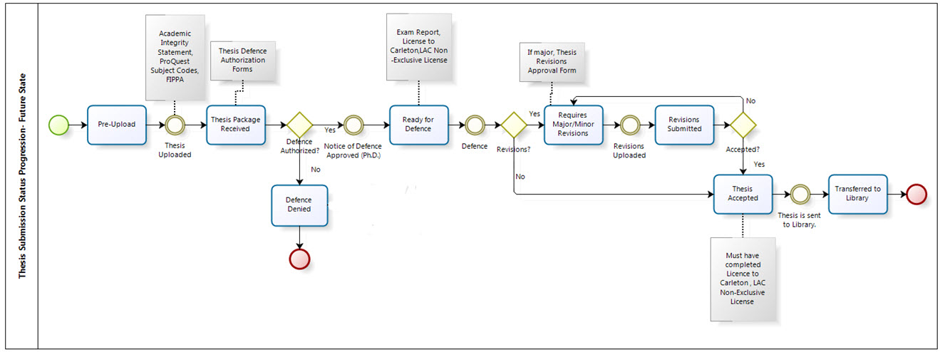
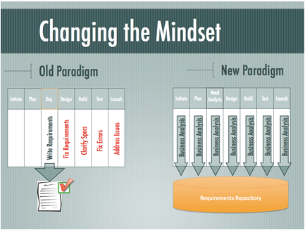
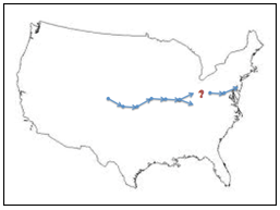
team completes a sprint (see Terre Haute, IN on the map) it evaluates if the same destination is still desired by the business sponsor.  If so, the development team will work with the next user story in the backlog.

Agile is a great concept and one that works well if it is done right.  But as the BA you need to prepare for the journey by addressing two major pitfalls in the way backlog requirements are defined and managed.  The first pitfall happens when functionality is added in such a way that only partially satisfies the business requirement.  The other pitfall occurs when there are two alternatives which need to be evaluated to determine which is best for the intended user.  Selecting the wrong fork may reduce the overall experience for the intended user, though the SCRUM team provided exactly what the business requested.

More comprehensive requirements with frequent validation will mitigate the risks associated with both of these pitfalls, but the approach requires a bit of time up front verifying the journey as it progresses.  If your team has a customer advocate or user experience expert, these resources should support your justification for taking a bit more time to revisit the roadmap.  Tools BAs can use for verifying the journey often take the form of a business process model or storyboard.  Using either method will force stakeholders to think at a higher level throughout the project—time well spent, especially if you get an “ah ha” moment.  Document the experience and testimonial.  You will be ready when a sponsor asks you to sprint a little faster.

Five Tactics To Help Support Your Arguments

  1. Localize your argument that bad requirements are directly tied to poor outcomes. Conduct an anecdotal or simple online survey at the beginning of a project. Ask each respondent to think about his or her last project and “guestimate” how many errors could’ve been avoided if the requirements were clearer up front. You can also ask them to directly tie a defect to a poorly-defined requirement.
  2. Recognize—and work within—the divide that exists between the business and IT. The expression to remember to use with both sides is “if you allow me to just spend a little more time” to clarify things for “those” folks, we will avoid headaches later.
  3. Avoid placing blame. Some people, such as stakeholders, hold interests that aren’t directly part of the solution so it is natural that your project and its deadlines may not get his or her full attention. But don’t complain. Most people have long memories and will remember your actions on the next project. A variation that does work is to approach the individual directly, asking for his or her help. When we do this we often find that the person needs to be involved sooner with more frequent, low time commitment reviews.
  4. Sponsor a learning session. Get the help of a member of the PMO to talk about the need to step away from the traditional “requirements as a checkbox” approach and toward the idea that requirements are a continual process.
  5. Use patience, praise and food. Even professionals need encouragement along the way especially when tasks cannot be done quickly and easily. And remember people always learn better when food is on the agenda, so quid pro quo could involve a wheat wrap or a chocolate chip cookie!

Don’t forget to leave your comments below.